PIC12CE67X
9.2
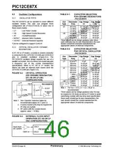
Oscillator Configurations
TABLE 9-1:
CAPACITOR SELECTION
FOR CERAMIC RESONATORS
- PIC12CE67X
9.2.1
OSCILLATOR TYPES
The PIC12CE67X can be operated in seven different
oscillator modes. The user can program three
configuration bits (FOSC2:FOSC0) to select one of
these seven modes:
Osc
Type
Resonator Cap. Range Cap. Range
Freq
C1
C2
XT
455 kHz
2.0 MHz
4.0 MHz
22-100 pF
15-68 pF
15-68 pF
22-100 pF
15-68 pF
15-68 pF
• LP:
• HS:
• XT:
Low Power Crystal
High Speed Crystal Resonator
Crystal/Resonator
HS
4.0 MHz
8.0 MHz
10.0 MHz
15-68 pF
10-68 pF
10-22 pF
15-68 pF
10-68 pF
10-22 pF
• INTRC*: Internal 4 MHz Oscillator
• EXTRC*: External Resistor/Capacitor
These values are for design guidance only. Since
each resonator has its own characteristics, the user
should consult the resonator manufacturer for
appropriate values of external components.
*Can be configured to support CLKOUT
9.2.2
CRYSTAL OSCILLATOR / CERAMIC
RESONATORS
TABLE 9-2:
CAPACITOR SELECTION
FOR CRYSTAL OSCILLATOR
- PIC12CE67X
In XT, HS or LP modes, a crystal or ceramic resonator
is connected to the GP5/OSC1/CLKIN and GP4/OSC2
pins to establish oscillation (Figure 9-2). The
PIC12CE67X oscillator design requires the use of a
parallel cut crystal. Use of a series cut crystal may give
Osc
Type
Resonator Cap.Range Cap. Range
Freq
C1
C2
(1)
LP
32 kHz
15 pF
15 pF
a
frequency out of the crystal manufacturers
100 kHz
200 kHz
15-30 pF
15-30 pF
30-47 pF
15-82 pF
specifications. When in XT, HS or LP modes, the
device can have an external clock source drive the
GP5/OSC1/CLKIN pin (Figure 9-3).
XT
100 kHz
200 kHz
455 kHz
1 MHz
2 MHz
4 MHz
15-30 pF
15-30 pF
15-30 pF
15-30 pF
15-30 pF
15-47 pF
200-300 pF
100-200 pF
15-100 pF
15-30 pF
15-30 pF
15-47 pF
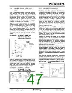
FIGURE 9-2: CRYSTAL OPERATION
(OR CERAMIC RESONATOR)
(XT, HS OR LP OSC
CONFIGURATION)
HS
4 MHz
8 MHz
10 MHz
15-30 pF
15-30 pF
15-30 pF
15-30 pF
15-30 pF
15-30 pF
(1)
C1
OSC1
PIC12CE67X
Note 1: For VDD > 4.5V, C1 = C2 ≈ 30 pF is
recommended.
SLEEP
XTAL
(3)
RF
To internal
logic
These values are for design guidance only. Rs may
be required in HS mode as well as XT mode to avoid
overdriving crystals with low drive level specification.
Since each crystal has its own characteristics, the
user should consult the crystal manufacturer for
appropriate values of external components.
OSC2
(2)
RS
(1)
C2
Note 1: See Capacitor Selection tables for
recommended values of C1 and C2.
2: A series resistor (RS) may be required for
AT strip cut crystals.
3: RF varies with the crystal chosen
(approx. value = 10 MΩ).
FIGURE 9-3: EXTERNAL CLOCK INPUT
OPERATION (XT, HS OR LP
OSC CONFIGURATION)
OSC1
OSC2
Clock from
ext. system
PIC12CE67X
Open
DS40181B-page 46
Preliminary
1998 Microchip Technology Inc.

 MICROCHIP [ MICROCHIP ]