ML4827
FUNCTIONAL DESCRIPTION
The ML4827 consists of an average current controlled,
continuous boost Power Factor Corrector (PFC) front end
and a synchronized Pulse Width Modulator (PWM) back
end. The PWM can be used in either current or voltage
mode. In voltage mode, feedforward from the PFC output
buss can be used to improve the PWM’s line regulation. In
either mode, the PWM stage uses conventional trailing-
edge duty cycle modulation, while the PFC uses leading-
edge modulation. This patented leading/trailing edge
modulation technique results in a higher useable PFC
error amplifier bandwidth, and can significantly reduce
the size of the PFC DC buss capacitor.
instantaneous amplitude, it will appear resistive to the AC
line and a unity power factor will be achieved.
To hold the input current draw of a device drawing power
from the AC line in phase with and proportional to the
input voltage, a way must be found to prevent that device
from loading the line except in proportion to the
instantaneous line voltage. The PFC section of the
ML4827 uses a boost-mode DC-DC converter to
accomplish this. The input to the converter is the full
wave rectified AC line voltage. No bulk filtering is
applied following the bridge rectifier, so the input voltage
to the boost converter ranges (at twice line frequency)
from zero volts to the peak value of the AC input and
back to zero. By forcing the boost converter to meet two
simultaneous conditions, it is possible to ensure that the
current which the converter draws from the power line
agrees with the instantaneous line voltage. One of these
conditions is that the output voltage of the boost converter
must be set higher than the peak value of the line
voltage. A commonly used value is 385VDC, to allow for
The synchronization of the PWM with the PFC simplifies
the PWM compensation due to the controlled ripple on
the PFC output capacitor (the PWM input capacitor). The
PWM section of both the ML4827-1 and the ML4827-2 run
at the same frequency as the PFC.
A number of protection features have been built into the
ML4827 to insure the final power supply will be as
reliable as possible. These include TriFault Detect, soft-
start, PFC over-voltage protection, peak current limiting,
brown-out protection, duty cycle limit, and under-voltage
lockout.
a high line of 270VAC . The other condition is that the
rms
current which the converter is allowed to draw from the
line at any given instant must be proportional to the line
voltage. The first of these requirements is satisfied by
establishing a suitable voltage control loop for the
converter, which in turn drives a current error amplifier
and switching output driver. The second requirement is
met by using the rectified AC line voltage to modulate
the output of the voltage control loop. Such modulation
causes the current error amplifier to command a power
stage current which varies directly with the input voltage.
In order to prevent ripple which will necessarily appear at
the output of the boost circuit (typically about 10VAC on
a 385V DC level) from introducing distortion back through
the voltage error amplifier, the bandwidth of the voltage
loop is deliberately kept low. A final refinement is to
adjust the overall gain of the PFC such to be proportional
to 1/VIN2, which linearizes the transfer function of the
system as the AC input voltage varies.
TRI-FAULTDETECTPROTECTION
Many power supplies manufactured for sale in the US
must meet Underwriter’s Laboratories (UL) standards. UL’s
specification UL1950 requires that no unsafe condition
may result from the failure of any single circuit
component. Typical system designs include external
active and passive circuitry to meet this requirement.
TriFault Detect is an on-chip feature of the ML4827 that
monitors the VFB pin for overvoltage, undervoltage, or
floating conditions which indicate that a component of
the feedback path may have failed. In such an event, the
PFC supply output will be disabled. These integrated
redundant protections assure system compliance with
UL1950 requirements.
Since the boost converter topology in the ML4827 PFC is
of the current-averaging type, no slope compensation is
required.
POWER FACTOR CORRECTION
Power factor correction makes a nonlinear load look like
a resistive load to the AC line. For a resistor, the current
drawn from the line is in phase with and proportional to
the line voltage, so the power factor is unity (one). A
common class of nonlinear load is the input of most
power supplies, which use a bridge rectifier and
capacitive input filter fed from the line. The peak-
charging effect which occurs on the input filter capacitor
in these supplies causes brief high-amplitude pulses of
current to flow from the power line, rather than a
sinusoidal current in phase with the line voltage. Such
supplies present a power factor to the line of less than one
(i.e. they cause significant current harmonics of the power
line frequency to appear at their input). If the input
current drawn by such a supply (or any other nonlinear
load) can be made to follow the input voltage in
PFC SECTION
Gain Modulator
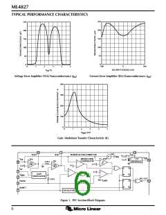
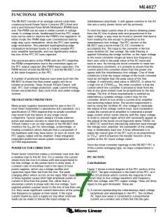
Figure 1 shows a block diagram of the PFC section of the
ML4827. The gain modulator is the heart of the PFC, as it
is this circuit block which controls the response of the
current loop to line voltage waveform and frequency,
RMS line voltage, and PFC output voltage. There are three
inputs to the gain modulator. These are:
1) A current representing the instantaneous input voltage
(amplitude and waveshape) to the PFC. The rectified
AC input sine wave is converted to a proportional
current via a resistor and is then fed into the gain
7

 MICRO-LINEAR [ MICRO LINEAR CORPORATION ]