KSZ8795CLX
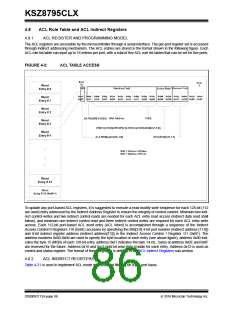
The VLAN table configuration is organized as 1024 VLAN sets, each VLAN set consists of four VLAN entries, to support
up to 4096 VLAN entries. Each VLAN set has total 60 bits and three reversed bits are inserted between entries. Actually,
52 bits are used for the VLAN set which should be read or written at the same time specified by the indirect address.
The VLAN entries in the VLAN set are mapped to indirect data registers as follow:
• Entry0[12:0] maps to the VLAN set Bits[12:0] {Register 119[4:0], Register 120[7:0]}
• Entry1[12:0] maps to the VLAN set Bits[28:16] {Register 117[4:0], Register 118[7:0]}
• Entry2[12:0] maps to the VLAN set Bits[44:32] {Register 115[4:0], Register 116[7:0]}
• Entry3[12:0] maps to the VLAN set Bits[60:48] {Register 113[4:0], Register 114[7:0]}
In order to read one VLAN entry, the VLAN set is read first and the specific VLAN entry information can be extracted.
To update any VLAN entry, the VLAN set is read first then only the desired VLAN entry is updated and the whole VLAN
set is written back. The FID in the VLAN table is 7 bits, so the VLAN table supports unique 128 flow VLAN groups. Each
VLAN set address is 10 bits long (Maximum is 1024) in the Indirect Address Register 110 and 111, the Bits[9:8] of VLAN
set address is at Bits[1:0] of Register 110, and the Bits[7:0] of VLAN set address is at bits [7:0] of Register 111. Each
Write and Read can access up to four consecutive VLAN entries.
Examples:
1. VLAN Table Read (read the VID = 2 entry)
Write the indirect control and address registers first
Write to Register 110 (0x6E) with 0x14 (read VLAN table selected)
Write to Register 111 (0x6F) with 0x0 (trigger the read operation for VID = 0, 1, 2, 3 entries)
Then read the Indirect Data Registers Bits[38:26] for VID = 2 entry
Read Register 115 (0x73), (Register 115 [4:0] are Bits[12:8] of VLAN VID = 2 entry)
Read Register 116 (0x74), (Register 116 [7:0] are Bits[7:0] of VLAN VID = 2 entry)
2. VLAN Table Write (write the VID = 10 entry)
Read the VLAN set that contains VID = 8, 9, 10, 11.
Write to Register 110 (0x6E) with 0x14 (read VLAN table selected)
Write to Register 111 (0x6F) with 0x02 (trigger the read operation and VID = 8, 9, 10, 11 indirect address)
Read the VLAN set first by the Indirect Data Registers 113, 114, 115, 116, 117, 118, 119, 120.
Modify the Indirect Data Registers Bits[44:32] by the Register 115 Bit[4:0] and Register 116 Bits[7:0] as follows:
Write to Register 115 (0x73), (Register115 [4:0] are Bits[12:8} of VLAN VID = 10 entry)
Write to Register 116 (0x74), (Register116 [7:0] are Bits[7:0] of VLAN VID = 10 entry)
Then write the indirect control and address registers
Write to Register 110 (0x6E) with 0x04 (write VLAN table selected)
Write to Register 111 (0x6F) with 0x02 (trigger the write operation and VID = 8, 9, 10, 11 indirect address)
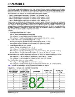
Table 4-18 shows the relationship of the indirect address/data registers and VLAN ID.
TABLE 4-18: VLAN ID AND INDIRECT REGISTERS
Indirect Address
High/Low Bit[9-0]
for VLAN Sets
Indirect Data
Registers Bits for
Each VLAN Entry
VID Bit[12-2] in
VLAN Tag
VID Bit[1-0] in
VLAN Tag
VID Numbers
0
0
0
0
1
1
1
1
2
Bits[12:0]
Bits[28:16]
Bits[44:32]
Bits[60:48]
Bits[12:0]
Bits[28:16]
Bits[44:32]
Bits[60:48]
Bits[12:0]
0
1
2
3
4
5
6
7
8
0
0
0
0
1
1
1
1
2
0
1
2
3
0
1
2
3
0
DS00002112A-page 82
2016 Microchip Technology Inc.

 MICREL [ MICREL SEMICONDUCTOR ]