KSZ8795CLX
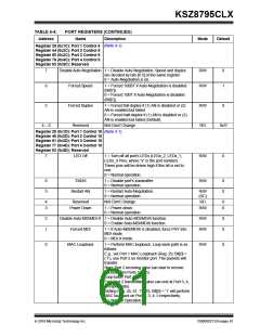
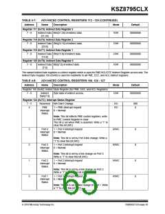
TABLE 4-4:
Address
PORT REGISTERS (CONTINUED)
Name Description
Mode
Default
Register 28 (0x1C): Port 1 Control 9 (Note 4-1)
Register 44 (0x2C): Port 2 Control 9
Register 60 (0x3C): Port 3 Control 9
Register 76 (0x4C): Port 4 Control 9
Register 92 (0x5C): Reserved
7
Disable Auto-Negotiation 1 = Disable Auto-Negotiation. Speed and duplex
R/W
R/W
0
1
are decided by bits [6:5] of the same register.
0 = Auto-Negotiation is on.
6
Forced Speed
Forced Duplex
Reserved
1 = Forced 100BT if Auto-Negotiation is disabled
(Bit[7]).
0 = Forced 10BT if Auto-Negotiation is disabled
(Bit[7]).
5
1 = Forced full-duplex if (1) AN is disabled or (2)
AN is enabled but failed.
0 = Forced half-duplex if (1) AN is disabled or (2)
AN is enabled but failed (Default).
R/W
RO
0
4 0
N/A Don’t Change.
0x1f
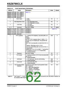
Register 29 (0x1D): Port 1 Control 10 (Note 4-1)
Register 45 (0x2D): Port 2 Control 10
Register 61 (0x3D): Port 3 Control 10
Register 77 (0x4D): Port 4 Control 10
Register 93 (0x5D): Reserved
7
LED Off
1 = Turn off all port’s LEDs (LEDx_2, LEDx_1,
LEDx_0 Pins, where “x” is the port number).
These pins will be driven high if this bit is set to
one.
R/W
R/W
0
0 = Normal operation.
6
5
TXIDS
1 = Disable port’s transmitter.
0 = Normal operation.
0
0
Restart AN
1 = Restart Auto-Negotiation.
0 = Normal operation.
R/W
(SC)
4
3
Reserved
N/A Don’t Change
RO
0
0
Power Down
1 = Power-down.
R/W
0 = Normal operation.
2
1
Disable Auto MDI/MDI-X 1 = Disable Auto-MDI/MDIX function.
0 = Enable Auto-MDI/MDIX function.
R/W
R/W
0
0
Forced MDI
1 = If Auto-MDI/MDIX is disabled, force PHY into
MDI mode.
0 = MDI-X mode.
0
MAC Loopback
1 = Perform MAC loopback. Loop back path is as
follows:
R/W
0
E.g., set Port 1 MAC Loopback (Reg. 29, Bit[0] =
(‘1’), use Port 2 as monitor port. The packets will
transfer.
Start: Port 2 receiving (also can start to receive
packets from Ports 3, 4, 5).
Loop-back: Port 1’s MAC.
End: Port 2 transmitting (also can end at Port 3, 4,
5 respectively).
Setting Reg. 45, 61, 77, 93, Bit[0] = ‘1’ will perform
MAC loopback on Port 2, 3, 4, 5 respectively.
0 = Normal Operation.
2016 Microchip Technology Inc.
DS00002112A-page 61

 MICREL [ MICREL SEMICONDUCTOR ]