Micrel, Inc.
KSZ9021RL/RN
LED Mode
The KSZ9021RL/RN provides two programmable LED output pins, LED2 and LED1, which are configurable to support
two LED modes. The LED mode is configured by the LED_MODE strap-in pin. It is latched at power-up/reset and is
defined as follows:
•
•
Pull-up:
Single LED Mode
Pull-down: Tri-color Dual LED Mode
Single LED Mode
In Single LED Mode, the LED2 pin indicates the link status while the LED1 pin indicates the activity status, as shown in
the following table.
LED pin
LED2
Pin State
LED Definition Link / Activity
H
OFF
Link off
L
ON
Link on (any speed)
No Activity
H
OFF
LED1
Toggle
Blinking
Activity (RX, TX)
Table 6. Single LED Mode – Pin Definition
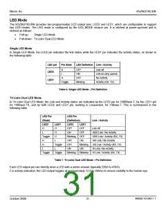
Tri-color Dual LED Mode
In Tri-color Dual LED Mode, the Link and Activity status are indicated by the LED2 pin for 1000Base-T, by the LED1 pin
for 100Base-TX, and by both LED2 and LED1 pin, working in conjunction, for 10Base-T. This is summarized in the
following table.
LED Pin
LED Pin
(State)
(Definition)
Link / Activity
LED2
LED1
LED2
OFF
LED1
H
H
OFF
Link off
L
H
ON
OFF
1000 Link / No Activity
1000 Link / Activity (RX, TX)
100 Link / No Activity
100 Link / Activity (RX, TX)
10 Link / No Activity
10 Link / Activity (RX, TX)
Toggle
H
Blinking
OFF
OFF
H
L
ON
H
Toggle
L
OFF
Blinking
ON
L
ON
Toggle
Toggle
Blinking
Blinking
Table 7. Tri-color Dual LED Mode – Pin Definition
Each LED output pin can directly drive a LED with a series resistor (typically 220Ω to 470Ω).
For activity indication, the LED output toggles at approximately 12.5Hz (80ms) to ensure visibility to the human eye.
M9999-101309-1.1
October 2009
31

 MICREL [ MICREL SEMICONDUCTOR ]