Micrel, Inc.
KSZ9021RL/RN
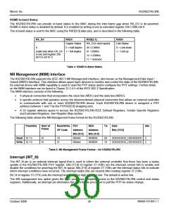
RGMII In-band Status
The KSZ9021RL/RN can provide in-band status to the MAC during the inter-frame gap when RX_DV is de-asserted.
RGMII in-band status is disabled by default. It is enabled by writing a one to extended register 256 (100h) bit 8.
The in-band status is sent to the MAC using the RXD[3:0] data pins, and is described in the following table.
RX_DV
RXD3
RXD[2:1]
RXD0
Duplex Status
0 = half-duplex
RX_CLK clock speed
00 =2.5MHz
Link Status
0 = Link down
1 = Link up
0
(valid only when RX_DV 1 = full-duplex
is low and register 256
01 =25MHz
10 =125MHz
11 = reserved
bit 8 is set to 1)
Table 4. RGMII In-Band Status
MII Management (MIIM) Interface
The KSZ9021RL/RN supports the IEEE 802.3 MII Management Interface, also known as the Management Data Input /
Output (MDIO) Interface. This interface allows upper-layer devices to monitor and control the state of the KSZ9021RL/RN.
An external device with MIIM capability is used to read the PHY status and/or configure the PHY settings. Further detail
on the MIIM interface can be found in Clause 22.2.4.5 of the IEEE 802.3 Specification.
The MIIM interface consists of the following:
•
•
A physical connection that incorporates the clock line (MDC) and the data line (MDIO).
A specific protocol that operates across the aforementioned physical connection that allows an external controller
to communicate with one or more KSZ9021RL/RN device. Each KSZ9021RL/RN device is assigned a PHY
address between 1 and 7 by the PHYAD[2:0] strapping pins.
•
A 32 register address space to access the KSZ9021RL/RN IEEE Defined Registers, Vendor Specific Registers
and Extended Registers. See Register Map section.
The following table shows the MII Management frame format for the KSZ9021RL/RN.
Preamble
Start of
Frame
Read/Write PHY
REG
TA
Data
Idle
OP Code
Address
Address
Bits [4:0]
RRRRR
RRRRR
Bits [15:0]
Bits [4:0]
00AAA
Read 32 1’s
01
01
10
01
Z0
10
DDDDDDDD_DDDDDDDD
DDDDDDDD_DDDDDDDD
Z
Z
Write 32 1’s
00AAA
Table 5. MII Management Frame Format – for KSZ9021RL/RN
Interrupt (INT_N)
The INT_N pin is an optional interrupt signal that is used to inform the external controller that there has been a status
update in the KSZ9021RL/RN PHY register. Bits [15:8] of register 27 (1Bh) are the interrupt control bits to enable and
disable the conditions for asserting the INT_N signal. Bits [7:0] of register 27 (1Bh) are the interrupt status bits to indicate
which interrupt conditions have occurred. The interrupt status bits are cleared after reading register 27 (1Bh).
Bit 14 of register 31 (1Fh) sets the interrupt level to active high or active low. The default is active low.
The MII management bus option gives the MAC processor complete access to the KSZ9021RL/RN control and status
registers. Additionally, an interrupt pin eliminates the need for the processor to poll the PHY for status change.
M9999-101309-1.1
October 2009
30

 MICREL [ MICREL SEMICONDUCTOR ]