Micrel, Inc.
KSZ9021RL/RN
Timing Recovery Circuit
In 1000Base-T mode, the mixed-signal clock recovery circuit, together with the digital phase locked loop, is used to
recover and track the incoming timing information from the received data. The digital phase locked loop has very low long-
term jitter to maximize the signal-to-noise ratio of the receive signal.
The 1000Base-T slave PHY is required to transmit the exact receive clock frequency recovered from the received data
back to the 1000Base-T master PHY. Otherwise, the master and slave will not be synchronized after long transmission.
Additionally, this helps to facilitate echo cancellation and NEXT removal.
Adaptive Equalizer
In 1000Base-T mode, the adaptive equalizer provides the following functions:
•
•
•
Detection for partial response signaling
Removal of NEXT and ECHO noise
Channel equalization
Signal quality is degraded by residual echo that is not removed by the analog hybrid and echo due to impedance
mismatch. The KSZ9021RL/RN employs a digital echo canceller to further reduce echo components on the receive signal.
In 1000Base-T mode, the data transmission and reception occurs simultaneously on all four pairs of wires (four channels).
This results in high frequency cross-talk coming from adjacent wires. The KSZ9021RL/RN employs three NEXT
cancellers on each receive channel to minimize the cross-talk induced by the other three channels.
In 10Base-T/100Base-TX mode, the adaptive equalizer needs only to remove the inter-symbol interference and recover
the channel loss from the incoming data.
Trellis Encoder and Decoder
In 1000Base-T mode, the transmitted 8-bit data is scrambled into 9-bit symbols and further encoded into 4D-PAM5
symbols. The initial scrambler seed is determined by the specific PHY address to reduce EMI when more than one
KSZ9021RL/RN is used on the same board. On the receiving side, the idle stream is examined first. The scrambler seed,
pair skew, pair order and polarity have to be resolved through the logic. The incoming 4D-PAM5 data is then converted
into 9-bit symbols and then de-scrambled into 8-bit data.
Functional Description: 10/100/1000 Transceiver Features
Auto MDI/MDI-X
The Automatic MDI/MDI-X feature eliminates the need to determine whether to use a straight cable or a crossover cable
between the KSZ9021RL/RN and its link partner. This auto-sense function detects the MDI/MDI-X pair mapping from the
link partner, and then assigns the MDI/MDI-X pair mapping of the KSZ9021RL/RN accordingly.
The following table shows the KSZ9021RL/RN 10/100/1000 pin-out assignments for MDI/MDI-X pin mapping.
MDI
100Base-TX
TX+/-
MDI-X
100Base-TX
RX+/-
Pin (RJ-45 pair)
1000Base-T
A+/-
10Base-T
TX+/-
1000Base-T
B+/-
10Base-T
RX+/-
TXRXP/M_A (1,2)
TXRXP/M_B (3,6)
TXRXP/M_C (4,5)
TXRXP/M_D (7,8)
B+/-
RX+/-
RX+/-
A+/-
TX+/-
TX+/-
C+/-
Not used
Not used
Not used
Not used
D+/-
Not used
Not used
Not used
Not used
D+/-
C+/-
Table 1. MDI / MDI-X Pin Mapping
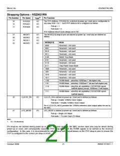
Auto MDI/MDI-X is enabled by default. It is disabled by writing a one to register 28 (1Ch) bit 6. MDI and MDI-X mode is
set by register 28 (1Ch) bit 7 if auto MDI/MDI-X is disabled.
An isolation transformer with symmetrical transmit and receive data paths is recommended to support auto MDI/MDI-X.
M9999-101309-1.1
October 2009
25

 MICREL [ MICREL SEMICONDUCTOR ]