Micrel, Inc.
KSZ9021RL/RN
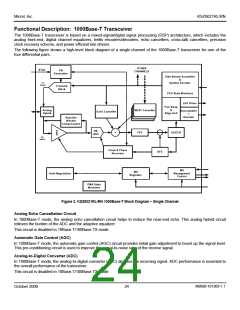
Functional Description: 1000Base-T Transceiver
The 1000Base-T transceiver is based on a mixed-signal/digital signal processing (DSP) architecture, which includes the
analog front-end, digital channel equalizers, trellis encoders/decoders, echo cancellers, cross-talk cancellers, precision
clock recovery scheme, and power efficient line drivers.
The following figure shows a high-level block diagram of a single channel of the 1000Base-T transceiver for one of the
four differential pairs.
OTHER
CHANNELS
XTAL
Clk
Generation
Side-Stream Scrambler
&
TX
Signal
Symbol Encoder
Transmit
Block
PCS State Machines
LED Driver
Pair Swap
&
Analog
Hybrid
NEXT Canceller
NEXT Canceller
NEXT Canceller
Descrambler
Echo Canceller
Align Unit
+
Decoder
Baseline
Wander
Compensation
RX-
ADC
FFE
SLICER
+
RX
Signal
Clock & Phase
Recovery
DFE
MII
MII
Registers
Auto-Negotiation
Management
Control
PMA State
Machines
Figure 2. KSZ9021RL/RN 1000Base-T Block Diagram – Single Channel
Analog Echo Cancellation Circuit
In 1000Base-T mode, the analog echo cancellation circuit helps to reduce the near-end echo. This analog hybrid circuit
relieves the burden of the ADC and the adaptive equalizer.
This circuit is disabled in 10Base-T/100Base-TX mode.
Automatic Gain Control (AGC)
In 1000Base-T mode, the automatic gain control (AGC) circuit provides initial gain adjustment to boost up the signal level.
This pre-conditioning circuit is used to improve the signal-to-noise ratio of the receive signal.
Analog-to-Digital Converter (ADC)
In 1000Base-T mode, the analog-to-digital converter (ADC) digitizes the incoming signal. ADC performance is essential to
the overall performance of the transceiver.
This circuit is disabled in 10Base-T/100Base-TX mode.
M9999-101309-1.1
October 2009
24

 MICREL [ MICREL SEMICONDUCTOR ]