Micrel, Inc.
KSZ9021RL/RN
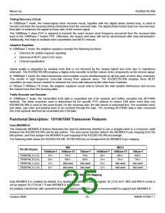
Strapping Options – KSZ9021RN
Type(1)
Pin Number
Pin Name
Pin Function
35
15
17
PHYAD2
PHYAD1
PHYAD0
I/O
The PHY Address, PHYAD[2:0], is latched at power-up / reset and is configurable to
any value from 1 to 7. Each PHY address bit is configured as follows:
I/O
Pull-up = 1
I/O
Pull-down = 0
PHY Address bits [4:3] are always set to ‘00’.
27
28
31
32
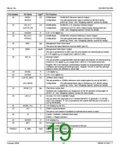
MODE3
MODE2
MODE1
MODE0
I/O
I/O
I/O
I/O
The MODE[3:0] strap-in pins are latched at power-up / reset and are defined as
follows:
MODE[3:0]
0000
0001
0010
0011
0100
0101
0110
0111
1000
1001
1010
1011
1100
1101
1110
Mode
Reserved – not used
Reserved – not used
Reserved – not used
Reserved – not used
NAND Tree Mode
Reserved – not used
Reserved – not used
Chip Power Down Mode
Reserved – not used
Reserved – not used
Reserved – not used
Reserved – not used
RGMII Mode – advertise 1000Base-T full-duplex only
RGMII Mode – advertise 1000Base-T full and half-duplex only
RGMII Mode – advertise all capabilities (10/100/1000 speed
half/full duplex),except 1000Base-T half-duplex
1111
RGMII Mode – advertise all capabilities (10/100/1000 speed
half/full duplex)
33
41
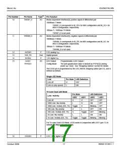
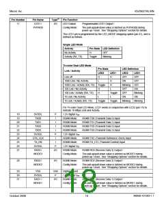
CLK125_EN
LED_MODE
I/O
I/O
CLK125_EN is latched at power-up / reset and is defined as follows:
Pull-up = Enable 125MHz Clock Output
Pull-down = Disable 125MHz Clock Output
Pin 41 (CLK125_NDO) provides the 125MHz reference clock output option for use by
the MAC.
LED_MODE is latched at power-up / reset and is defined as follows:
Pull-up = Single LED Mode
Pull-down = Tri-color Dual LED Mode
Note:
1. I/O = Bi-directional.
Pin strap-ins are latched during power-up or reset. In some systems, the MAC receive input pins may be driven during
power-up or reset, and consequently cause the PHY strap-in pins on the RGMII signals to be latched to the incorrect
configuration. In this case, it is recommended to add external pull-ups/pull-downs on the PHY strap-in pins to ensure the
PHY is configured to the correct pin strap-in mode.
M9999-101309-1.1
October 2009
21

 MICREL [ MICREL SEMICONDUCTOR ]