Micrel, Inc.
KSZ9021RL/RN
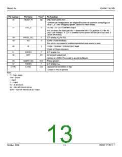
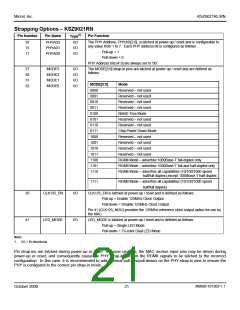
Pin Number
Pin Name
Type(1)
Pin Function
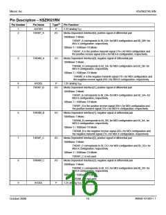
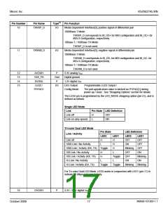
10
TXRXP_D
I/O
Media Dependent Interface[3], positive signal of differential pair
1000Base-T Mode:
TXRXP_D corresponds to BI_DD+ for MDI configuration and BI_DC+ for
MDI-X configuration, respectively.
10Base-T / 100Base-TX Mode:
TXRXP_D is not used.
11
TXRXM_D
I/O
Media Dependent Interface[3], negative signal of differential pair
1000Base-T Mode:
TXRXM_D corresponds to BI_DD- for MDI configuration and BI_DC- for
MDI-X configuration, respectively.
10Base-T / 100Base-TX Mode:
TXRXM_D is not used.
3.3V analog VDD
12
13
14
15
AVDDH
VSS_PS
DVDDL
LED2 /
P
Gnd
P
Digital ground
1.2V digital VDD
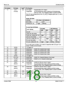
I/O
LED Output:
Config Mode:
Programmable LED2 Output /
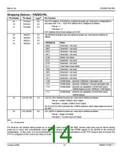
PHYAD1
The pull-up/pull-down value is latched as PHYAD[1] during
power-up / reset. See “Strapping Options” section for details.
The LED2 pin is programmed by the LED_MODE strapping option (pin 41), and is
defined as follows.
Single LED Mode
Link
Pin State LED Definition
Link off
H
L
OFF
ON
Link on (any speed)
Tri-color Dual LED Mode
Link / Activity
Pin State
LED Definition
LED2
LED1
LED2
OFF
LED1
Link off
H
L
H
OFF
1000 Link / No Activity
H
ON
OFF
1000 Link / Activity (RX, TX) Toggle
H
Blinking
OFF
OFF
100 Link / No Activity
H
L
ON
100 Link / Activity (RX, TX)
10 Link / No Activity
H
Toggle
L
OFF
Blinking
ON
L
ON
10 Link / Activity (RX, TX)
Toggle
Toggle
Blinking
Blinking
For Tri-color Dual LED Mode, LED2 works in conjunction with LED1 (pin 17) to
indicate 10 Mbps Link and Activity.
16
DVDDH
P
3.3V / 2.5V digital VDD
M9999-101309-1.1
October 2009
17

 MICREL [ MICREL SEMICONDUCTOR ]