MIC4421/4422
Micrel, Inc.
To guarantee low supply impedance over a wide frequency
range, a parallel capacitor combination is recommended for
supply bypassing. Low inductance ceramic disk capacitors
with short lead lengths (< 0.5 inch) should be used.A1µF low
ESRfilmcapacitorinparallelwithtwo0.1µFlowESRceramic
Applications Information
Supply Bypassing
Charging and discharging large capacitive loads quickly
requires large currents. For example, charging a 10,000pF
load to 18V in 50ns requires 3.6A.
®
capacitors, (such as AVX RAM Guard ), provides adequate
bypassing. Connect one ceramic capacitor directly between
pins 1 and 4. Connect the second ceramic capacitor directly
between pins 8 and 5.
The MIC4421/4422 has double bonding on the supply pins,
the ground pins and output pins. This reduces parasitic
lead inductance. Low inductance enables large currents to
be switched rapidly. It also reduces internal ringing that can
cause voltage breakdown when the driver is operated at or
near the maximum rated voltage.
Grounding
The high current capability of the MIC4421/4422 demands
careful PC board layout for best performance. Since the
MIC4421 is an inverting driver, any ground lead impedance
willappearasnegativefeedbackwhichcandegradeswitching
speed. Feedback is especially noticeable with slow-rise time
inputs. The MIC4421 input structure includes about 200mV
of hysteresis to ensure clean transitions and freedom from
oscillation, but attention to layout is still recommended.
Internal ringing can also cause output oscillation due to
feedback. This feedback is added to the input signal since it
is referenced to the same ground.
V
S
Figure 5 shows the feedback effect in detail. As the MIC4421
input begins to go positive, the output goes negative and
several amperes of current flow in the ground lead. As little
as 0.05Ω of PC trace resistance can produce hundreds of
millivolts at the MIC4421 ground pins. If the driving logic is
referenced to power ground, the effective logic input level is
reduced and oscillation may result.
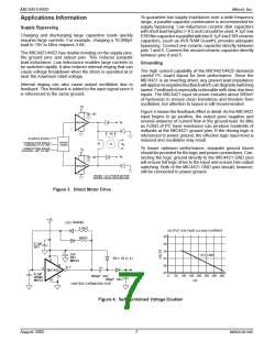
1µF
V
MIC4451
S
Ø
2
Ø
DRIVE SIGNAL
1
DRIVE
LOGIC
CONDUCTION ANGLE
CONTROL 0° TO 180°
Ø
M
Ø
3
1
To insure optimum performance, separate ground traces
should be provided for the logic and power connections. Con-
necting the logic ground directly to the MIC4421 GND pins
will ensure full logic drive to the input and ensure fast output
switching. Both of the MIC4421 GND pins should, however,
still be connected to power ground.
CONDUCTION ANGLE
CONTROL 180° TO 360°
V
S
V
1µF
S
MIC4452
PHASE 1 of 3 PHASE MOTOR
DRIVER USING MIC4420/4429
Figure 3. Direct Motor Drive
+15
(x2) 1N4448
5.6kΩ
OUTPUT VOLTAGE vs LOAD CURRENT
30
560 Ω
0.1µF
50V
29
28
+
1µF
12 Ω LIN
E
50V
BYV 10 (x 2)
27
26
25
1
MKS2
8
6, 7
+
2
MIC4421
0.1µF
WIMA
MKS2
+
0
50 100 150 200 250 300 350
mA
5
560µF 50V
100µF 50V
4
UNITED CHEMCON SXE
Figure 4. Self Contained Voltage Doubler
August 2005
7
M9999-081005

 MIC [ MIC GROUP RECTIFIERS ]