MX25L12835F
9-4. Release from Deep Power-down (RDP), Read Electronic Signature (RES)
The Release from Deep Power-down (RDP) instruction is completed by driving Chip Select (CS#) High. When Chip
Select (CS#) is driven High, the device is put in the Stand-by Power mode. If the device was not previously in the
Deep Power-down mode, the transition to the Stand-by Power mode is immediate. If the device was previously in
the Deep Power-down mode, though, the transition to the Stand-by Power mode is delayed by tRES2, and Chip Se-
lect (CS#) must remain High for at least tRES2(max), as specified in "Table 17. AC CHARACTERISTICS". Once in
the Stand-by Power mode, the device waits to be selected, so that it can receive, decode and execute instructions.
The RDP instruction is only for releasing from Deep Power Down Mode. Reset# pin goes low will release the Flash
from deep power down mode.
RES instruction is for reading out the old style of 8-bit Electronic Signature, whose values are shown as "Table 6. ID
Definitions". This is not the same as RDID instruction. It is not recommended to use for new design. For new de-
sign, please use RDID instruction.
Even in Deep power-down mode, the RDP and RES are also allowed to be executed, only except the device is in
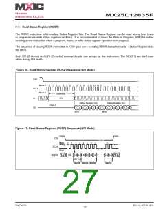
progress of program/erase/write cycle; there's no effect on the current program/erase/write cycle in progress.
Both SPI (8 clocks) and QPI (2 clocks) command cycle can accept by this instruction. The SIO[3:1] are don't care
when during SPI mode.
The RES instruction is ended by CS# goes high after the ID been read out at least once. The ID outputs repeat-
edly if continuously send the additional clock cycles on SCLK while CS# is at low. If the device was not previously
in Deep Power-down mode, the device transition to standby mode is immediate. If the device was previously in
Deep Power-down mode, there's a delay of tRES2 to transit to standby mode, and CS# must remain to high at least
tRES2(max). Once in the standby mode, the device waits to be selected, so it can be receive, decode, and execute
instruction.
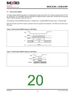
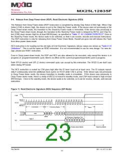
Figure 11. Read Electronic Signature (RES) Sequence (SPI Mode)
CS#
Mode 3
Mode 0
0
1
2
3
4
5
6
7
8
9
10
28 29 30 31 32 33 34 35 36 37 38
SCLK
Command
ABh
t
3 Dummy Bytes
RES2
SI
23 22 21
MSB
3
2
1
0
Electronic Signature Out
High-Z
7
6
5
4
3
2
0
1
SO
MSB
Deep Power-down Mode
Stand-by Mode
P/N: PM1795
REV. 1.0, OCT. 23, 2012
23

 Macronix [ MACRONIX INTERNATIONAL ]