MX25L12835F
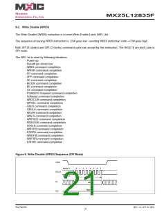
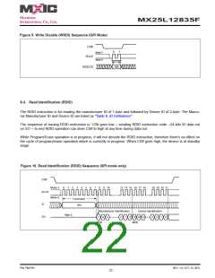
Figure 9. Write Disable (WRDI) Sequence (QPI Mode)
CS#
0
1
Mode 3
SCLK
Mode 0
Command
SIO[3:0]
04h
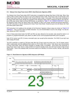
9-3. Read Identification (RDID)
The RDID instruction is for reading the manufacturer ID of 1-byte and followed by Device ID of 2-byte. The Macro-
nix Manufacturer ID and Device ID are listed as "Table 6. ID Definitions".
The sequence of issuing RDID instruction is: CS# goes low→ sending RDID instruction code→24-bits ID data out
on SO→ to end RDID operation can drive CS# to high at any time during data out.
While Program/Erase operation is in progress, it will not decode the RDID instruction, therefore there's no effect on
the cycle of program/erase operation which is currently in progress. When CS# goes high, the device is at standby
stage.
Figure 10. Read Identification (RDID) Sequence (SPI mode only)
CS#
0
1
2
3
4
5
6
7
8
9
10
13 14 15 16 17 18
28 29 30 31
Mode 3
Mode 0
SCLK
SI
Command
9Fh
Manufacturer Identification
Device Identification
High-Z
SO
7
6
5
2
1
0
15 14 13
MSB
3
2
1
0
MSB
P/N: PM1795
REV. 1.0, OCT. 23, 2012
22

 Macronix [ MACRONIX INTERNATIONAL ]