Trip le -Ou t p u t P o w e r-S u p p ly
Co n t ro lle r fo r No t e b o o k Co m p u t e rs
MAX782
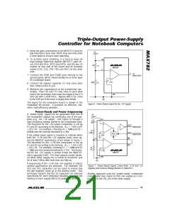
When active, outputs Q1-Q3 pull up to VH. Resistor
________Eva lu a t io n Kit In fo rm a t io n
R16, located on the back of the board, pulls the high-
side driver voltage VH up to +15V. By removing R16
and installing a resistor at the empty R15 site, VH may
be tied to the +3.3V output. Alternately, both R15 and
R16 may be omitted and the user may supply an arbi-
trary voltage between 3V and 20V at the VH edge pad.
Note that Q1-Q3 are not meant to drive high-current
loads directly.
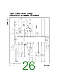
The MAX782 evaluation kit (EV kit) is an assembled,
surface-mount demonstration board. The kit embodies
the standard application circuit and uses dip switches
to control the 3V, 5V, and VPP outputs. The board
accepts battery input voltages between 6.5V and 30V,
and provides up to 30W of output power. All functions
are controlled by standard CMOS/TTL logic levels.
___________Ev Kit Qu ic k Re fe re n c e
To set up the EV kit, use the following procedure:
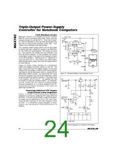
The D1-D3 comparators can be used as precision volt-
age detectors by installing resistor dividers at each
input (R11/R12, R10/R13, R9/R14).
1. Connect a power supply to the BATT IN terminals.
The supply voltage should be between 6.5V and 30V.
Input current may be several amps, depending on the
input voltage and the output power demanded.
P o w e r-S u p p ly Co n t ro ls
ON3 – Enable 3.3V power supply
ON5 – Enable 5.0V power supply
2. Turn on the +5V outp ut b y s e tting the ON5 d ip
switch to ON. The 5V OUT edge pad now supplies
+5V at up to 3A, and +15V is now available at the
+15V OUT edge pad.
SYNC – Switch-mode power-supply frequency input
(optional)
VP P Vo lt a g e Ou t p u t s
The PCMCIA-compatible programmable voltage out-
puts are controlled by the DA0, DA1, DB0, and DB1
logic-level inputs. The MAX782 provides industry-
standard Intel 82365-comptaible VPPA/VPPB PCMCIA
c ontrols (s e e Pin De s c rip tion). The four-c irc uit d ip
s witc h c onne c ts the s a me wa y a s the e d g e p a d s .
From left to right, switch 1 controls DA1, switch 2 con-
trols DA0, switch 3 controls DB1, and switch 4 controls
DB0. VPPA and VPPB are capable of supplying 60mA
each.
3. Turn on the +3.3V output by setting the ON3 dip
switch to ON. The 3.3V OUT edge pad now sup-
plies +3.3V at up to 3A. The two regulators may be
operated independently.
4. To use the VPPA/VPPB programmable voltage out-
puts, ON5 must be enabled. Set the four-circuit dip
switch to the desired code and measure the output at
the VPPA and VPPB edge pads. DA0 and DA1 con-
trol VPPA’s state; DB0 and DB1 control VPPB’s state.
_______Ev Kit De t a ile d De s c rip t io n
Ba t t e ry In p u t
BATT IN – Battery input, 6.5V to 30V
GND – Ground
The battery input voltage should be between 6.5V and
30V. The input voltage upper limit is set by the voltage
rating of the input bypass capacitors, C1 and C13, and
may not exceed the MAX782’s 30V maximum rating.
Higher input voltages generally require physically larg-
er input capacitors.
Lo w -Ba t t e ry De t e c t io n Co m p a ra t o rs
To demonstrate the level shifters / high-side drivers,
ON5 must be enabled so the +15V (VDD) is available
to pull up the Q1-Q3 outputs. Measure the high-side
driver supply at the VH edge pad. Logic-level edge
pads D1-D3 control the outputs Q1-Q3. Q1-Q3 pull up
to VH whenever the corresponding input D1-D3 is at a
logic-high level.
______________________________________________________________________________________ 25

 MAXIM [ MAXIM INTEGRATED PRODUCTS ]