5 V, Lo w -P o w e r, Vo lt a g e -Ou t p u t ,
S e ria l 1 0 -Bit DACs
04/MAX15
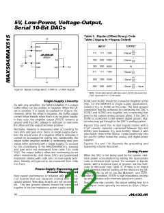
CS CLR DIN DOUT REFOUT V
V
SS
DD
2.048V
5
4
3
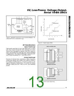
POSITIVE OFFSET
NEGATIVE OFFSET
SIGNAL
IN
REFIN
VOUT
INVERTED
R-2R DAC
2R
2R
RFB
2
1
BIPOFF
MAX504
0
1
2
3
4
5
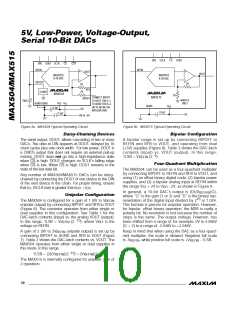
Figure 9. MAX504 Connected as Four-Quadrant Multiplier. The
unused REFOUT is connected to V
.
DD
DAC CODE (LSBs)
Figure 10. Single-Supply Offset
AC Co n s id e ra t io n s
ANALOG GROUND PLANE
Digital Feedthrough
High-speed serial data at any of the digital input or output
pins may couple through the DAC package and cause
internal stray capacitance to appear at the DAC output as
noise, even though CS is held high (see Typical Operating
Characteristics). This digital feedthrough is tested by hold-
ing CS high transmitting 0101... from DIN to DOUT.
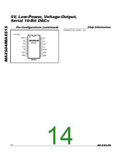
0.1µF
1
2
3
4
5
6
7
14
13
12
11
10
9
Analog Feedthrough
Because of internal stray capacitance, higher frequency
analog input signals may couple to the output as shown in
the Analog Feedthrough vs. Frequency graph in the
Typical Operating Characteristics. It is tested by holding
CS high, setting the DAC code to all 0s, and sweeping
REFIN.
0.1µF
8
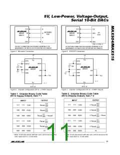
(a) MAX504 BYPASSING
1
8
7
6
5
2
3
4
0.1µF
(b) MAX515 BYPASSING
Figure 11. Power-Supply Bypassing
______________________________________________________________________________________ 13

 MAXIM [ MAXIM INTEGRATED PRODUCTS ]