Low-Cost Multichemistry Battery Chargers
CCV, CCI, CCS, and LVC Control Blocks
The MAX1908/MAX8724 control input current (CCS
control loop), charge current (CCI control loop), or
charge voltage (CCV control loop), depending on the
operating condition.
Current Measurement
Use ICHG to monitor the battery charging current being
sensed across CSIP and CSIN. The ICHG voltage is
proportional to the output current by the equation:
V
= I
x RS2 x G
x R9
ICHG
CHG
ICHG
The three control loops, CCV, CCI, and CCS are brought
together internally at the LVC amplifier (lowest voltage
clamp). The output of the LVC amplifier is the feedback
control signal for the DC-DC controller. The output of the
where I
is the battery charging current, G
is
CHG
ICHG
the transconductance of ICHG (3µA/mV typ), and R9 is
the resistor connected between ICHG and ground.
Leave ICHG unconnected if not used.
G
amplifier that is the lowest sets the output of the LVC
M
Use IINP to monitor the system input current being
sensed across CSSP and CSSN. The voltage of IINP is
proportional to the input current by the equation:
amplifier and also clamps the other two control loops to
within 0.3V above the control point. Clamping the other
two control loops close to the lowest control loop ensures
fast transition with minimal overshoot when switching
between different control loops.
V
= I
x RS2 x G
x R10
IINP
INPUT
IINP
where I
is the DC current being supplied by the AC
INPUT
adapter power, G
is the transconductance of IINP
IINP
DC-DC Controller
The MAX1908/MAX8724 feature a variable off-time, cycle-
by-cycle current-mode control scheme. Depending upon
the conditions, the MAX1908/MAX8724 work in continu-
ous or discontinuous-conduction mode.
(3µA/mV typ), and R10 is the resistor connected between
IINP and ground. ICHG and IINP have a 0 to 3.5V output
voltage range. Leave IINP unconnected if not used.
LDO Regulator
LDO provides a 5.4V supply derived from DCIN and
can deliver up to 10mA of load current. The MOSFET
drivers are powered by DLOV and BST, which must be
connected to LDO as shown in Figure 1. LDO supplies
the 4.096V reference (REF) and most of the control cir-
cuitry. Bypass LDO with a 1µF capacitor to GND.
Continuous-Conduction Mode
With sufficient charger loading, the MAX1908/MAX8724
operate in continuous-conduction mode (inductor current
never reaches zero) switching at 400kHz if the BATT
voltage is within the following range:
3.1V x (number of cells) < V
< (0.88 x V
)
DCIN
BATT
Shutdown
The MAX1908/MAX8724 feature a low-power shutdown
mode. Driving SHDN low shuts down the MAX1908/
MAX8724. In shutdown, the DC-DC converter is dis-
abled and CCI, CCS, and CCV are pulled to ground.
The IINP and ACOK outputs continue to function.
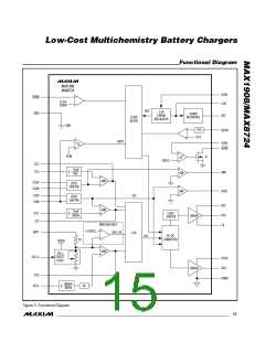
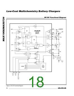
The operation of the DC-DC controller is controlled by
the following four comparators as shown in Figure 4:
IMIN—Compares the control point (LVC) against 0.15V
(typ). If IMIN output is low, then a new cycle cannot
begin.
CCMP—Compares the control point (LVC) against the
charging current (CSI). The high-side MOSFET on-time
is terminated if the CCMP output is high.
SHDN can be driven by a thermistor to allow automatic
shutdown of the MAX1908/MAX8724 when the battery
pack is hot. The shutdown falling threshold is 23.5%
(typ) of V
with 1% V
hysteresis to provide
REFIN
REFIN
IMAX—Compares the charging current (CSI) to 6A
(RS2 = 0.015Ω). The high-side MOSFET on-time is ter-
minated if the IMAX output is high and a new cycle
cannot begin until IMAX goes low.
smooth shutdown when driven by a thermistor.
DC-DC Converter
The MAX1908/MAX8724 employ a buck regulator with
a bootstrapped NMOS high-side switch and a low-side
NMOS synchronous rectifier.
ZCMP—Compares the charging current (CSI) to 33mA
(RS2 = 0.015Ω). If ZCMP output is high, then both
MOSFETs are turned off.
______________________________________________________________________________________ 17

 MAXIM [ MAXIM INTEGRATED PRODUCTS ]