NOTE: All part numbers
are RoHS Compliant
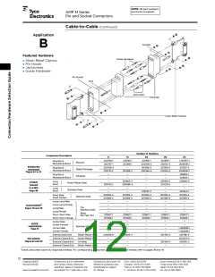
AMP M Series
Pin and Socket Connectors
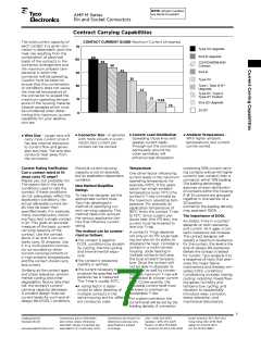
Presentation - Example of New Current Rating Format
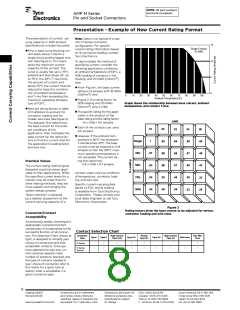
The presentation of current- car-
rying capacity in AMP product
specifications includes two parts:
Note: Data is not typical of a spe-
cific M Series connector
configuration. For specific
15
Single Contact
18 AWG
current rating information based
on % connector loading, contact
Tyco Electronics.
First, a base curve showing cur-
rent levels versus T-rise for a
single circuit and the largest wire
size (See figure 1). This repre-
sents the maximum current
capacity of the contact. The
curve is usually flat up to 75°C
ambient and then drops off. Up
to 75°C, the 30°C T-rise limits
the amount of current, and
above 75°C the current must be
reduced to keep the combina-
tion of ambient temperature
and T-rise from exceeding the
maximum operating tempera-
ture of 105°C.
10
5
To demonstrate the method of
specifying current, consider the
following application conditions;
an ambient temperature of 65°C, a
50% loading of contacts in the
2
housing, and 20 AWG [0.6mm ]
wire.
From Figure 1, the base current
rating is 14 ampere with 18 AWG
0
2
[0.8mm ] wire.
0
10
20
30
40
50
60
70
80
90
100
Ambient Temperature (C)
Figure 2, the rating factor for
50% loading and 20 AWG
Graph shows the relationship between base current, ambient
temperature, and contact T-rise.
2
[0.6mm ] wire is 0.68.
Next are rating factors; a table
of multipliers to account for
connector loading and for
smaller wire sizes (See figure 2).
The designer first determines
the base current for the ambi-
ent conditions of the
application; then multiplies this
base current by the rating fac-
tors to find the current level for
the application’s loading factor
and wire size.
The specific rating for this appli-
cation is the product of the
base rating and the rating factor:
14 x 0.68 = 9.5 ampere
AWG
Each of the contacts can carry
9.5 ampere.
18
1
20
.83
.80
.68
.53
.45
22
.69
.66
.57
.45
.38
24
.59
.57
.48
.38
.32
26
.50
.49
.42
.33
.28
However, if the ambient tem-
perature is 80°C the allowable
T-rise becomes 25°C. The base
current must be lowered to 12.8
ampere so that the 105°C maxi-
mum operating temperature is
not exceeded. The current rat-
ing then becomes:
Single
30%
.97
.83
.65
.55
Practical Values
12.8 x 0.68 = 8.7 ampere.
50%
The current-rating method gives
designers practical values appli-
cable to their applications. While
the specified current levels for a
contact may be lower than for
other testing methods, they are
more realistic and simplify the
system design process.
contact under varying conditions
of temperature, connector load-
ing, and wire size.
70%
Specific current-carrying data
based on EOL and % loading
is available from Tyco Electronics
Corporation. Please contact your
local Sales Engineer or call Tyco
Electronics Corporation.
100%
“Spec-manship” is replaced
by a realistic assessment of the
current-carrying capacity of a
Figure 2
Rating factors allow the base current to be adjusted for various
connector loading and wire sizes.
Connector/Contact
Acceptability
As previously stated, choosing the
appropriate connector/contact
combination is fundamental to the
successful function of all connec-
tors. The Selection Chart, shown at
right, is designed to simplify your
choice of connectors and their
acceptable contacts. Once you
have selected the wire size, cur-
rent-carrying capacity need,
Contact Selection Chart
Connector
Type
High Current
Type II/III
Posted
Type III+
High Current
Type XII
Sub-Mini
Coax
Type I
Type II
Type III+
Type XII
Mini-coax
M Series
M Series
Special
number of positions required, and
the type of contacts needed in
your choice of connector, refer to
this matrix for a quick look at
exactly what is acceptable in a
given connector type.
8
Catalog 82003
Revised 06-08
Dimensions are in millimeters
and inches unless otherwise
specified. Values in brackets are
equivalent U.S. Customary Units.
Dimensions are shown for
reference purposes only.
Specifications subject
to change.
USA: 1-800-522-6752
South America: 55-11-3611-1514
Hong Kong: 852-2735-1628
Japan: 81-44-844-8013
UK: 44-141-810-8967
Canada: 1-905-470-4425
Mexico: 01-800-733-8926
C. America: 52-55-5-729-0425
www.tycoelectronics.com

 MACOM [ Tyco Electronics ]