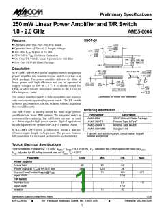
250 mW Linear Power Amplifier and T/R Switch
AM55-0004
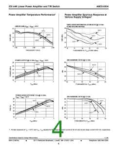
Transmit/Receive Switch Performance
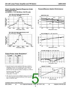
Power Amplifier Spectral Response Under
Modulation Drive
(π/4 DQPSK, ␣ = 0.5, 384 kB/sec, 9-bit PN code)
SPECTRAL RESPONSE UNDER MODULATION1
INSERTION LOSS
(V = 3.0 V, P
= 20.5 dBm)
D
OUT
0.0
-0.5
-1.0
-1.5
-2.0
0
-20
-40
-60
-80
-15°C
+25°C
+70°C
1899.0
1899.4
1899.8
1900.2
1900.6
1901.0
1.50
1.75
2.00
FREQUENCY (GHz)
2.25
2.50
FREQUENCY (MHz)
SPECTRAL RESPONSE UNDER MODULATION1
(V = 4.8 V, P
= 23.4 dBm)
ISOLATION (@ -15°C, +25°C and +70°C)
D
OUT
0
-10
-20
-30
-40
-50
-60
-70
-20
-25
-30
-35
-40
1.50
1.75
2.00
2.25
2.50
1899.0
1899.4
1899.8
1900.2
1900.6
1901.0
FREQUENCY (GHz)
FREQUENCY (MHz)
RETURN LOSS (@ -15°C, +25°C and +70°C)
0
-5
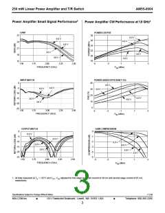
Output Power Under Modulation2
-10
-15
-20
-25
-30
-35
In
VD (volts)
POUT (dBm)
20.5
Out
3
3.6
4
21.4
22.2
4.8
6
23.4
23.7
1.5 1.6 1.7 1.8
1.9
2.0 2.1
2.2
2.3 2.4
2.5
FREQUENCY (GHz)
1. Spectral output is tested under the following conditions:
Modulation scheme is π/4 DQPSK with a bit transfer rate
of 384 kB/sec and a root Nyquist filter with ␣ = 0.5 per
RCR STD-28. The spectrum analyzer settings are as follows:
LINEARITY (Tx MODE)
33
31
29
27
25
23
2.5
1.5
0.5
Resolution bandwidth: 10 kHz
Video bandwidth: 100 kHz
Sweep time: 5 seconds
-0.5
-1.5
-2.5
2. This chart documents the modulated output power delivered
for a fixed adjacent channel interference (ACI) rejection of 55
dBc at a 600-kHz offset.
25 26 27 28
29 30 31 32 33 34
POWER IN (dBm)
Specifications Subject to Change Without Notice
V 2.00
M/A-COM Inc.
■
1011 Pawtucket Boulevard, Lowell, MA 01853 USA
■
Telephone: 800-366-2266
5

 TE [ TE CONNECTIVITY ]