SXT6051 Functional Timing
Transmit Frame Serial Timing
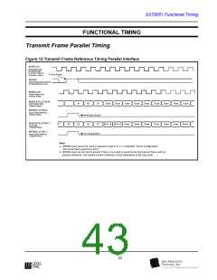
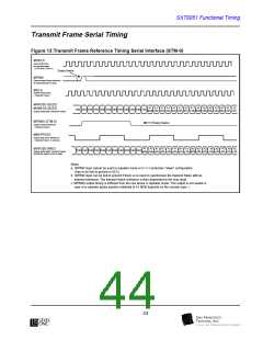
Figure 13:Transmit Frame Reference Timing Serial Interface (STM-0)
MHICLK
Input serial clock
for transmit frame
(
51.84 MHz / STM -0 )
Every fram e
MFRMI
External input frame reference
for transmit frame (8 KHz)
MICLK
Output Serial Clock
(
Transmit Frame)
MHPOSD (B3ZS)
A1
A1
A1
A1
A1
A1
A1
A1
A2
A2
A2
A2
A2
A2
A2
bit1
MHNEGD (B3ZS)
D ata
D ata D ata D ata
D ata D ata D ata D ata D ata D ata D ata D ata
MS B bit6 bit5 bit4 bit3 bit2 bit1 LSB MS B bit6 bit5 bit4 bit3 bit2
Output Serial data (Transmit Frame)
MFRMO (STM-0)
Output Frame Reference
Every fram e
(
Transmit Frame)
MM SPPCKO
Output Byte Clock Reference
(
Transmit Frame : 6.48 M Hz)
MHPOSD (NRZ)
A1
MS B bit6
A1
A1
bit2
A2
bit2
A1
A1
A1
A1
A1
A2
A2
A2
A2
bit4 bit3
A2
A2
bit1 LSB
A2
D ata D ata D ata D ata D ata D ata D ata D ata D ata D ata D ata
Output Serial data( Transmit Frame)
(M HNEG D output is tied to high)
bit5 bit4 bit3
bit1 LSB MS B bit6 bit5
Notes :
a. M FRM I input cannot be used in repeater m ode or in 1+1 protection "slave" configuration.
(has to be tied to ground or VCC)
b. M FRM I input can be tied to ground if there is no need to synchronize the transm it fram e with an
external reference. The transm it fram e reference is then dependent to the chip reset.
c. MFRMO output tim ing is different from the one above in repeater m ode. This output is not usable in
case of a repeater (pulse position relatively to A1 MSB depends on the receiver sync. )
44

 LevelOne [ LEVEL ONE ]