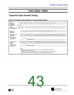
Functional Timing
byte locations can be filled by a 0 or
1 but not tri-stated.
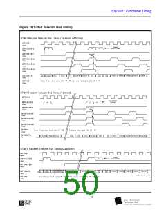
Telecom Bus Interface
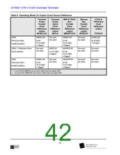
The SXT6051 follows the industry standard Telecom Bus
to interface with other SDH products, including the
SXT6251. The standard is based on the original work of the
IEEE P1396 project, which never made it to final approval.
SFT has enhanced the bus to be compatible with other stan-
dard SDH products on the market.
MTBPAR
MTBCKO
MTBDATA<7:0> parity check. An odd
parity calculation accompanies each data
byte input (including the bytes filling the
SOH, AUP and HPOH locations).
Telecom Bus byte clock output (6.48
MHz in STM-0 and 19.44 MHz in STM-
1 mode). This clock is the same as the
Multiplexer transmit frame clock output
(MHBCLKO).
Multiplexer Telecom Bus Terminal
Mode
In this mode, the Telecom Bus is a contra-directional inter-
face. This means the SXT6051 generates the timing refer-
ences (clock and signals) and receives the synchronized
data.
MTBCKI
Not used in terminal mode (should be
tied to ground).
MTBPAYEN A High on this output indicates the loca-
tion of the VC-4 (STM-1 mode) or the
VC-3 with two stuffed columns (STM-0
mode) on the Multiplexer Telecom Bus.
A Low indicates the location of the SOH
bytes and the AU Pointers bytes.
Note on Telecom Bus
Timing Reference
All transitions of the Telecom bus Timing
references (MTBH4EN, MTBPAYEN,
MTBJ0EN and MTBTUGEN) are in phase with
the rising edge of MTBCKO, and the incoming
data (MTBPAR & MTBDATA<7:0>) are
clocked by the falling edge of this clock.
MTBH4EN
An output that indicates the multi-frame
start position. This signal is High during
one complete frame every four frames
and Low for the remaining three frames
The Low to High or High to Low transi-
tion occurs at the H4 location, and the
MTBH4EN output is High on the J1 byte
position following the “00” value of H4.
Note on Multi-Frame
Synchronization
The transmit multi-frame can be synchronized by
using an external 2 KHz reference signal
connected to the MMFRMI input pin. This
synchronization input signal can only be active
High for a single frame and must be synchronous
with MTBCLKO or MHBCKO outputs.
MTBJ0J1EN
An output that indicates J0 and J1 bytes
locations relative to the SXT6051 Trans-
mit Frame synchronization as there is no
AU pointer movements and no re-timing
functions in Terminal mode (AU pointer
equal to value 0). MTBJ0J1EN can be
configured via register 71H in two ways:
It is possible to synchronize several transmitters
by cascading the synchronization: Connect the
output MTBH4EN of one chip (chip #1) to the
input MMFRMI of a second chip (chip #2), etc. If
no synchronization is required, MMFRMI must
be grounded.
•A single pulse at J0 position and a sin-
gle pulse at J1 position.
•A single pulse at J0 position, a single
pulse at J1 position and a double pulse
on J1 every four frames to indicate the
V1 position.
This Telecom Bus is comprised of the following signals:
MTBDATA<7:0> Byte wide input data with either
STM-1 or STM-0 frame structure
MTBTUGEN1 A High indicates the location of TUG3
#1, plus the position of the VC-4 POH
depending on STMMODE selec-
tion. Only the C-4 (in STM-1) or C-
bytes. In STM-0 this output is tied High.
MTBTUGEN2 A High indicates the location of TUG3
3 (in STM-0) bytes are relevant. The
#2, plus the position of the VC-4 POH
SOH Byte, AU Pointers and HPOH
46
l

 LevelOne [ LEVEL ONE ]