SXT6051 STM-1/0 SDH Overhead Terminator
DTBCK
Telecom Bus byte clock output 6.48
MHz (STM-0) and 19.44 MHz (STM-1)
mode.
DTBPAYEN
A High on this output indicates the pres-
ence of the VC-4 (STM1 mode) or the
VC-3 with two stuffed columns (STM0
mode). A Low indicates the presence of
the SOH bytes and the AU Pointers’
bytes.
DTBH4EN
Output indicates the multi-frame start
position. This signal is High during one
complete frame every four frames and
Low for the remaining three frames The
Low to High or High to Low transition
occurs at the H4 location, and the
MTBH4EN output is High on the J1 byte
position following the “00” value of H4.
DTBJ0J1EN
Output indicates J0 and J1 byte locations
relative to the receive signal.
MTBJ0J1EN can be configured via reg-
ister 81H in two ways:
•A single pulse at J0 position and a sin-
gle pulse at J1 position indicates when
the frame and the payload starts.
•A single pulse at J0 position, a single
pulse at J1 position and a double pulse
on J1 every four frames indicating a
multiframe.
DTBTUGEN1 A High on this output indicates the loca-
tion of TUG3 #1, plus the presence of the
VC-4 POH bytes. In STM-0 this output
is tied High.
DTBTUGEN2 A High on this output indicates the loca-
tion of TUG3 #2, plus the presence of the
VC-4 POH bytes (but not the stuffed col-
umn) In STM-0 this output is tied High.
DTBTUGEN3 A High on this output indicates the loca-
tion of TUG3 #3, plus the presence of the
VC-4 POH bytes (but not the stuffed col-
umn) In STM-0 this output is tied High.
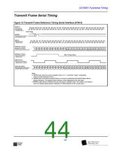
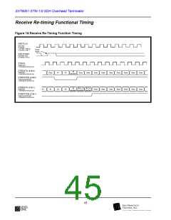
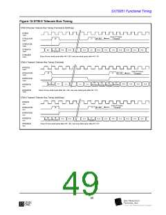
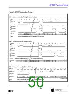
Figures 15 and 16 show the relation of timing reference and
data signals on the Telecom bus.
48

 LevelOne [ LEVEL ONE ]