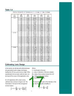
For thin lenses, it is a good approximation to
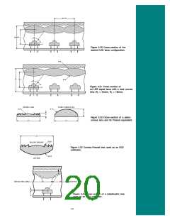
A cross-section through the center of a plano-
convex lens, and its Fresnel counterpart are
shown in Figure 5.32.
measure f from the center of the lens.
For thin, plano-convex lenses (R1 = ¥ ), the
equation further simplifies to:
The thickness of the Fresnel lens is reduced as
the number of steps is increased. Typically Fresnel
lenses are designed with the minimum number of
steps needed to achieve the desired thickness,
because additional light losses may occur at the
internal faces and joining vertices. However, for
plastic lenses, a thin design is desirable where
excessive lens thickness will result in sink
distortions. Therefore, the performance and
moldability of a lens are traded-off when choosing
the optimal number of steps.
The above equations assume all rays arrive at
shallow angles with respect to the optical axis
(paraxial assumption). However, for SuperFlux
LED applications, where much of the flux is
contained at angles far from the optical axis,
this is not the case. As a result, rays which are
not close to the optical axis will be bent at too
great an angle, a condition known as spherical
aberration. A correction factor, C, can be added
to the above equations to compensate for this
effect as shown below:
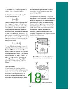
For most LED collimator designs, a correction
factor of C @ 1.35 will produce the best results.
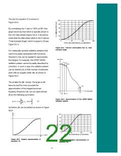
The value of f chosen can be checked by
tracing a ray from the source to the outer edge
of the collimator lens (edge ray). If the edge ray
is under collimated, the value of C used is too
large. If the edge ray is over collimated, the
value of C used is too small. Figure 5.29
graphically depicts the edge ray method for
checking f.
Figure 5.28 Cross-section of an LED signal
lamp using a dual-convex, collimator lens.
Fresnel Lens Design
A Fresnel lens can be visualized as a thick
convex lens which has been collapsed about a
series of circular, stepped setbacks. This type
of lens takes on the properties of a much
thicker lens and eliminates the difficulties
involved with the manufacture of thick lenses.
Figure 5.29 Edge ray method for checking f.
18

 LUMILEDS [ LUMILEDS LIGHTING COMPANY ]