Reflector Design
Reflector cavities serve two main purposes: to
redirect the light from the LED into a useful
beam pattern, and to provide a unique
appearance for the finished lamp. Often the look
sought after is not achievable by the most
optically efficient design. As a result, there is a
trade-off required between optical efficiency
and lit appearance to arrive at an acceptable
design.
the reflector. Once the parabola has been
designed, a cavity with a profile comprised of
multiple linear sections that closely approximates
the form of the parabola may be used depending
on the look desired.
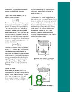
In order to accommodate the SuperFlux LED
dome, the bottom aperture of the reflector must
be greater than three-millimeters in diameter.
Considering the tolerances of the molded
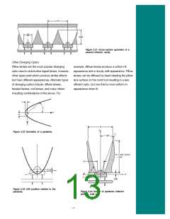
As discussed in the previous section Point
Source Optical Model, a parabola is designed
to collimate the light from the point source. For
reflector, the LED, the LED alignment to the PCB,
and the alignment of the reflector to the PCB, the
bottom reflector aperture should be a minimum of
the design technique discussed here, the LED is 3.5 mm in diameter. The focal length of the
treated as a point source. This treatment is very
accurate for larger parabolas where the size of
the dome is small relative to the exit aperture of
reflector must be greater than 0.5 mm to produce
a bottom aperture of greater than 3.5 mm.
Design Case—Reflector for a CHMSL Application
Consider the case where a reflector cavity will be used to
collimate the light from an HPWT-MH00 source, and a
pillow optic cover lens will be used to form the final radiation
pattern. Vacuum-metalized ABS plastic will be used as the
reflector material. The reflector cavity can be a maximum of
20 mm in height and should have a minimum opening for
the LED dome of diameter 3.75mm to accommodate piece-
part misalignment and tolerances. The LED spacing is 15
mm, and each cell must illuminate a 15 mm x 15 mm patch
on the pillow lens. Figure 5.21 shows a cross-section of the
lamp described above. The geometry of a parabola, in polar
coordinates, is described by the following equation:
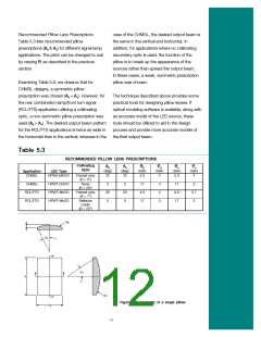
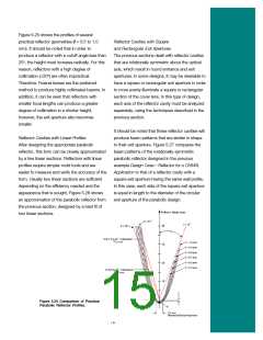
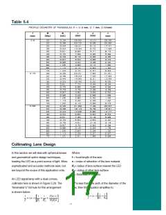
Table 5.4 describes the profiles of three different parabolas
(f = 0.9 mm, 0.7 mm, 0.66 mm).
An efficient, practical collimator design for a CHMSL
application should collimate all the light beyond 20°?from on
axis (f £ 20°). More efficient reflectors can be designed which
collimate more of the light, but they are typically too deep to be
of practical value.
The ideal reflector for this application will have the following
characteristics:
Height constraint: 0.99 £ z £ 20 mm
Fit of LED dome into bottom aperture:x (z = 0.99 mm) ³ ?1.875
mm
Figure 5.22 shows how the terms in this equation are
applied.
15 mm pitch: x (F = 20°) @?7.5 mm
From Table 5.1, we find that the optimum point source
location for the HPWT-MH00 LED is at Z = 0.99 mm.
Placing the point source of the LED at the focus of the
parabola will result in an LED position as shown in Figure
5.23.
Looking at Table 5.4, we find that the parabola with f = 0.66
mm most closely meets these requirements. Figure 5.24 gives
the geometry of the parabolic reflector chosen.
Since the base of the LED dome is above the location of the
parabola’s focus, this implies that 2f < 1/2 base aperture =
3.75 mm/2 = 1.875 mm (f < 0.94 mm). This information will
give us a starting point to begin searching for the optimum
parabola.
14

 LUMILEDS [ LUMILEDS LIGHTING COMPANY ]