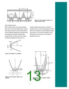
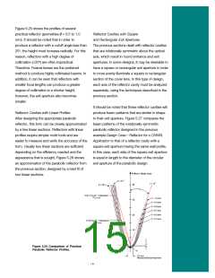
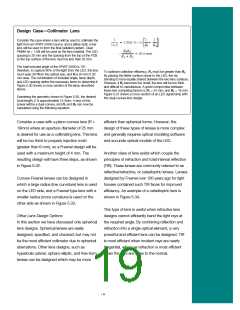
Figure 5.25 shows the profiles of several
practical reflector geometries (f = 0.5 to 1.0
mm). It should be noted that in order to
produce a reflector with a cutoff angle less than
20°, the height must increase radically. For this
reason, reflectors with a high degree of
collimation (<20°) are often impractical.
Therefore, Fresnel lenses are the preferred
method to produce highly collimated beams. In
addition, it can be seen that reflectors with
smaller focal lengths can produce a greater
degree of collimation in a shorter height,
however, the exit aperture also becomes
smaller.
Reflector Cavities with Square
and Rectangular Exit Apertures
The previous sections dealt with reflector cavities
that are rotationally symmetric about the optical
axis, which result in round entrance and exit
apertures. In some designs, it may be desirable to
have a square or rectangular exit aperture in order
to more evenly illuminate a square or rectangular
section of the cover lens. In this type of design,
each axis of the reflector cavity must be analyzed
separately, using the techniques described in the
previous section.
It should be noted that these reflector cavities will
produce beam patterns that are similar in shape
to their exit aperture. Figure 5.27 compares the
beam patterns of the rotationally-symmetric
parabolic reflector designed in the previous
example Design Case—Reflector for a CHMSL
Application to that of a reflector cavity with a
square exit aperture having the same wall profile.
In this case, each side of the square exit aperture
is equal in length to the diameter of the circular
exit aperture of the parabolic design.
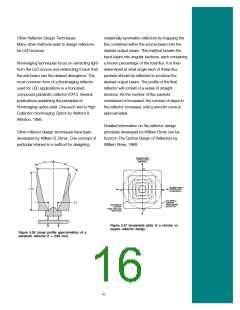
Reflector Cavities with Linear Profiles
After designing the appropriate parabolic
reflector, this form can be closely approximated
by a few linear sections. Reflectors with linear
profiles require simpler mold tools and are
easier to measure and verify the accuracy of the
form. Usually two linear sections are sufficient
depending on the efficiency needed and the
appearance that is sought. Figure 5.26 shows
an approximation of the parabolic reflector from
the previous section, designed by a best fit of
two linear sections.
_
Figure 5.25 Comparison of Practical
Parabolic Reflector Profiles.
15

 LUMILEDS [ LUMILEDS LIGHTING COMPANY ]