ST150S
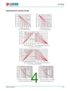
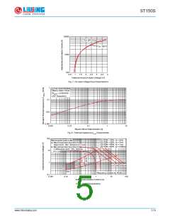
PERFORMANCE CURVES FIGURE
130
130
120
110
100
90
R
(DC) = 0.105 K/ W
R
(DC) = 0.105 K/ W
thJC
thJC
120
110
100
90
Conduction Pe riod
Conduction Angle
30°
30°
60°
80
60°
90°
90°
120°
120°
DC
180°
180°
80
70
0
50
100 150 200 250 300
0
50 100 150 200 250 300 350 400 450
Average On-state Current (A)
Average On-state Current (A)
Fig. 1 - Current Ratings Characteristics
Fig. 2 - Current Ratings Characteristics
350
R
180°
120°
300
=
0
90°
60°
.
1
K
/
0
W
.
2
250
30°
5
-
K
D
/
W
e
0
l
t
a
.
3
K
R
/
W
200
RM S Limit
150
0
.
6
K
/
Conduction Angle
W
W
100
50
0
1
.
2
K
/
T = 125°C
J
0
50
100 150 200 250
3
2
0
5
0
50
75
100
125
Maximum Allowable Ambient Te mperature (°C)
Average On-state Current (A)
Fig. 3 - On-state Power Loss Characteristics
500
450
400
350
300
250
200
150
100
50
DC
180°
120°
90°
0
.
0
t
6
h
K
S
A
0
/
.
0
W
8
K
/
W
60°
0
.
1
6
30°
K
/
W
0
.
2
K
/
W
0
.
3
K
/
W
RM S Limit
Conduction Pe riod
0
.
6
K
/
W
1
K
/
W
T = 125°C
J
0
0
50 100 150 200 250 300 350 400 4
Average On-state Current (A)
Fig. 4 - On-state Power Loss Characteristics
2
5
5
0
50
75
100
125
Maximum Allowable Ambient Te mperature (°C)
7000
6500
6000
5500
5000
4500
4000
3500
3000
7000
6500
6000
5500
5000
4500
4000
3500
3000
At Any Ra ted Lo ad Condition And With
At Any Ra ted Lo ad Condition And With
Ra ted V
RRM
Applied Fo llowing Su rge.
Ra ted V Applied Fo llowing Su rge.
RRM
Initial T = 125°C
Initial T = 125°C
J
@ 60 Hz 0.0083 s
@ 50 Hz 0.0100 s
J
@ 60 Hz 0.0083 s
@ 50 Hz 0.0100 s
1
10
100
1
10
100
NumberOf Eq ual Amplitude Ha lf Cycle Current Pulses(N)
NumberOf Eq ual Amplitude Ha lf Cycle Current Pulses(N)
Fig. 5 - Maximum Non-Repetitive Surge Current
Fig. 6 - Maximum Non-Repetitive Surge Current
www.china-liujing.com
4 / 6

 LIUJING [ 浙江柳晶整流器有限公司 ]