LT3505
APPLICATIONS INFORMATION
capacitorandasmallSchottkydiode(suchastheBAT-54).
For lower output voltages tie a Schottky diode to the input
(Figure6b).ThecircuitinFigure6aismoreefficientbecause
theBOOSTpincurrentcomesfromalowervoltagesource.
You must also be sure that the maximum voltage rating
of the BOOST pin is not exceeded.
of the BOOST pin.
At light loads, the inductor current becomes discontinu-
ous and the effective duty cycle can be very high. This
reduces the minimum input voltage to approximately
400mV above VOUT. At higher load currents, the inductor
current is continuous and the duty cycle is limited by the
maximum duty cycle of the LT3505, requiring a higher
input voltage to maintain regulation.
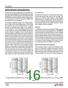
The minimum operating voltage of an LT3505 applica-
tion is limited by the undervoltage lockout (3.6V) and by
the maximum duty cycle as outlined above. For proper
start-up, the minimum input voltage is also limited by
the boost circuit. If the input voltage is ramped slowly,
or the LT3505 is turned on with its SHDN pin when the
output is already in regulation, then the boost capacitor
may not be fully charged. Because the boost capacitor is
charged with the energy stored in the inductor, the circuit
will rely on some minimum load current to get the boost
circuit running properly. This minimum load will depend
on the input and output voltages and on the arrangement
of the boost circuit. The minimum load generally goes to
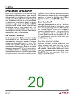
zero once the circuit has started. Figure 7 shows a plot of
minimum load to start and to run as a function of input
voltage. In many cases the discharged output capacitor
will present a load to the switcher which will allow it to
start. The plots show the worst-case situation where VIN
is ramping verly slowly. For lower start-up voltage, the
boost diode can be tied to VIN; however this restricts the
input range to one-half of the absolute maximum rating
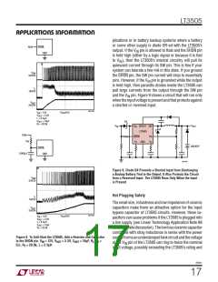
Soft-Start
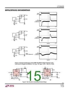
TheSHDNpincanbeusedtosoft-starttheLT3505,reducing
themaximuminputcurrentduringstart-up. TheSHDNpin
is driven through an external RC filter to create a voltage
ramp at this pin. Figure 8 shows the start-up waveforms
with and without the soft-start circuit. By choosing a large
RCtimeconstant, thepeakstartupcurrentcanbereduced
to the current that is required to regulate the output, with
no overshoot. Choose the value of the resistor so that it
can supply 20µA when the SHDN pin reaches 2.3V.
Shorted and Reversed Input Protection
If the inductor is chosen so that it won’t saturate exces-
sively, an LT3505 buck regulator will tolerate a shorted
output. There is another situation to consider in systems
where the output will be held high when the input to the
LT3505 is absent. This may occur in battery charging ap-
7.2
5.5
T
= 25°C
T
= 25°C
A
A
7.0
6.8
6.6
5.3
5.1
4.9
TO START
TO START
6.4
6.2
4.7
4.5
6.0
5.8
5.6
5.4
5.2
4.3
4.1
3.9
3.7
3.5
TO RUN
TO RUN
1
10
100
1000
1
10
100
1000
LOAD CURRENT (mA)
LOAD CURRENT (mA)
3505 G15
(7a) Typical Minimum Input Voltage, VOUT = 5V, fSW = 750kHz
(7b) Typical Minimum Input Voltage, VOUT = 3.3V, fSW = 750kHz
Figure 7
3505fc
16

 Linear [ Linear ]