LTC6820
applicaTions inForMaTion
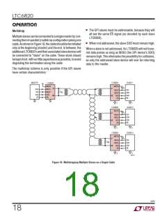
isoSPI Setup
For cables over 50 meters:
I = 1mA
The LTC6820 allows each application to be optimized for
power consumption or for noise immunity. The power
and noise immunity of an isoSPI system is determined
by the programmed I current. The I current can range
B
V = (20 • I ) • (R /2)
A
B
M
V
V
= 1/4 • V
TCMP
ICMP
A
B
B
from 0.1mA to 1mA. A low I reduces the isoSPI power
B
= 2 • V
TCMP
consumption in the READY and ACTIVE states, while a
R
B2
= V
/I
ICMP B
high I increases the amplitude of the differential signal
B
voltage V across the matching termination resistor, R .
A
M
2V
RB1 =
–RB2
I is programmed by the sum of the R and R resis-
I
B
B1
B2
B
tors connected between the I
pin and GND. For most
BIAS
The maximum data rate of an isoSPI link is determined by
the length of the cable used. For cables 10 meters or less
the maximum 1MHz SPI clock frequency is possible. As
the length of the cable increases the maximum possible
SPI clock rate decreases. This is a result of the increased
propagation delays through the cable creating possible
timing violations.
applications setting I to 0.5mA is a good compromise
B
between power consumption and noise immunity. Using
this I setting with a 1:1 transformer and R = 120Ω, R
B
M
B1
should be set to 2.8k and R set to 1.2k. In a typical CAT5
B2
twisted pair these settings will allow for communication
up to 50m.
For applications that require cables longer than 50m it is
Cabledelayaffectsthreetimingspecifications,t ,t ,and
recommended to increase the amplitude V by increasing
CLK 6
A
t . IntheElectricalCharacteristicstable, eachisderatedby
I to 1mA. This compensates for the increased insertion
7
B
100ns to allow for 50ns of cable delay. For longer cables,
the minimum timing parameters may be calculated as
shown below:
loss in the cable and maintains high noise immunity. So
when using cables over 50m and, again, using a trans-
former with a 1:1 turns ratio and R = 120Ω, R would
M
B1
be 1.4k and R would be 600Ω.
B2
t
, t , and t > 0.9µs + 2 • t
6 7 CABLE
CLK
OtherI settingscanbeusedtoreducepowerconsumption
B
Pull-Up Resistance Considerations
or increase the noise immunity as required by the applica-
tion. In these cases when setting V
and choosing R
ICMP
B1
The data output (MOSI if MSTR = 0, MISO if MSTR = 1)
andR resistorvaluesthefollowingrulesshouldbeused:
B2
requires a pull-up resistor, R . The rise time t
is
PU
PU
RISE
determined by R and the capacitance on the pin. R
PU
For cables 50 meters or less:
must be small enough to provide adequate setup and hold
times. For a slave device, the time constant must be less
than t and t . In fast mode, 50ns is recommended.
I = 0.5mA
B
V = (20 • I ) • (R /2)
12
14
A
B
M
R
< 50ns/C
LOAD
V
V
= 1/2 • V
PU
TCMP
ICMP
A
Larger pull-up resistances, up to 5k, can be used in slow
mode.
= 2 • V
TCMP
R
= V
/I
B2
ICMP B
2V
RB1 =
–RB2
I
B
6820f
19

 Linear [ Linear ]