LTC6820
applicaTions inForMaTion
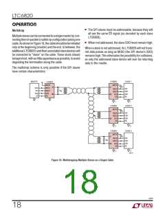
Layout of the isoSPI signal lines also plays a significant
role in maximizing the immunity of a circuit. The following
layout guidelines should be followed:
BCI test injects current into the twisted-pair lines at set
levels over a frequency range of 1MHz to 400MHz. With
the minimum I current, 0.1mA, the isoSPI serial link has
B
been shown to pass a 40mA BCI test with no bit errors.
A 40mA BCI test level is sufficient for most industrial ap-
plications. Automotive applications tend to have a higher
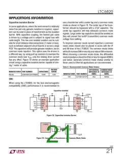
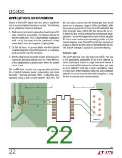
1. ThetransformershouldbeplacedasclosetotheisoSPI
cable connector as possible. The distance should be
kept less than 2cm. The LTC6820 should be placed at
least 1cm to 2cm away from the transformer to help
isolate the IC from the magnetic coupling fields.
BCIrequirementsotherecommendedI issetto1mA, the
B
maximumpowerlevel.TheisoSPIsystemhasbeenshown
to pass a 200mA BCI test with no transmitted bit errors.
The 200mA test level is typical for automotive testing.
2. On the top layer, no ground plane should be placed
underthemagnetic,theisoSPIconnector,orinbetween
the transformer and the connector.
Software Layer
3. TheIPandIMtracesshouldbeisolatedfromsurround-
ing circuits. No traces should cross the IP and IM lines,
unless separated by a ground plane within the printed
circuit board.
The isoSPI physical layer has high immunity to EMI and
is not particularly susceptible to bit errors induced by
noise, but for best results in a high noise environment it
is recommended to implement a software layer that uses
an error detection code like a cyclic redundancy check
or check sum. Error detection codes will allow software
detection of any bit error and will notify the system to retry
the last erroneous serial communication.
The isoSPI drive currents are programmable and allow
for a tradeoff between power consumption and noise
immunity. The noise immunity of the LTC6820 has been
evaluated using a bulk current injection (BCI) test. The
1.5cm
1cm
IP
IM
CONNECTOR
6820 F20
Figure 20. Example Layout
6820f
22

 Linear [ Linear ]