LTC6820
operaTion
Table 5. IDD Equations
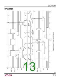
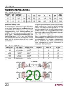
Figure 15 demonstrates a simple procedure for waking
a master (MSTR = 1) LTC6820 and its connected slave
(MSTR = 0). A negative edge on CS causes the master
to drive IBIAS to 2V and, after a short delay, transmit a
STATE
MSTR
0 (slave)
1 (master)
0 or 1
ESTIMATED I
2µA
DD
IDLE
1µA
long +1 pulse. (If CS remains low throughout t
, the
READY
READY
ACTIVE
1.7mA + 3 • I
B
LTC6820 would first generate a –1 pulse, then the +1
pulse when CS returns high). The long pulse serves as a
wake-up signal for the slave device, which responds by
driving its IBIAS pin to 2V and entering the READY state.
0 (slave)
100ns•0.5
2mA+ 3+20•
•IB
tCLK
1 (master)
100ns
tCLK
2mA+ 3+20•
•IB
240mV
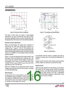
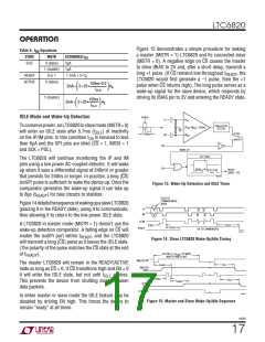
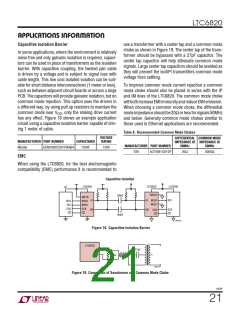
IDLE Mode and Wake-Up Detection
To conservepower,anLTC6820inslavemode(MSTR=0)
IP
IP
AC
240ns DELAY
(FILTER)
|IP –IM | > 240mV
AC
AC
AC
will enter an IDLE state after 5.7ms (t
) of inactivity
IDLE
SLAVE
240ns
IM
IM
on the IP/IM pins. In this condition I is reduced to less
DD
MASTER
than 6µA and the SPI pins are idled (CS = 1, MOSI = 1
CS
WAKE-UP
and SCK = POL).
IDLE TIMER
The LTC6820 will continue monitoring the IP and IM
pins using a low power AC-coupled detector. It will wake
up when it sees a differential signal of 240mV or greater
that persists for 240ns or longer. In practice, a long (CS)
isoSPI pulse is sufficient to wake the device up. Once the
comparator generates the wake-up signal it can take up
EN
t
READY
READY
(IBIAS = 2V)
t
IDLE
6820 F13
Figure 13. Wake-Up Detection and IDLE Timer
to 8µs (t
) for bias circuits to stabilize.
READY
REJECTS
COMMON MODE
NOISE
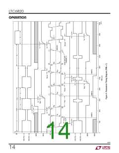
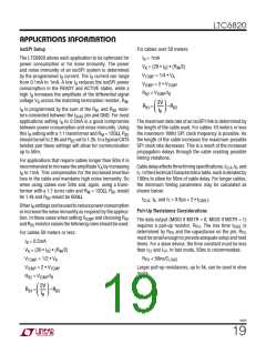
Figure14detailsthesequenceofwakingupaslaveLTC6820
(placing it in the READY state), using it to communicate,
then allowing it to return to the low power IDLE state.
IP
IM
IP-IM
A LTC6820 in master mode (MSTR = 1) doesn’t use the
t
t
IDLE
DWELL
t
READY
READY
OK TO COMMUNICATE
wake-up detection comparator. A falling edge on CS will
6820 F14
enable the isoSPI port within t , and the LTC6820
READY
Figure 14. Slave LTC6820 Wake-Up/Idle Timing
will transmit a long (CS) pulse as it leaves the IDLE state.
(The polarity of the pulse matches the CS state at the end
ALLOW >2 • t TO WAKE
MASTER AND SLAVE
READY
of t
).
READY
MASTER CS
The master LTC6820 will remain in the READY/ACTIVE
t
t
IDLE
READY
MASTER
IBIAS
state as long as CS = 0. If CS transitions high and EN = 0
IP-IM
it will enter the IDLE state, but not until t
expires.
IDLE
t
DWELL
t
IDLE
t
READY
This prevents the device from shutting down between
SLAVE
IBIAS
data packets.
SLAVE CS
6820 F15
In either master or slave mode the IDLE feature may be
disabled by driving EN high. This forces the device to
remain “ready” at all times.
Figure 15. Master and Slave Wake-Up/Idle Sequence
6820f
17

 Linear [ Linear ]