LTC6820
operaTion
ISOLATION BARRIER
MSTR
LTC6820
IP
IP
MSTR
LTC6820
MASTER
SLAVE
SDI
SDO
SCK
CS
R
R
M
M
SDO
SDI
SCK
CS
MOSI
IM
IM
IBIAS
MOSI
MISO
SCK
CS
TWISTED-PAIR CABLE
WITH CHARACTERISTIC IMPEDANCE R
MISO IBIAS
SCK
M
R
R
R
R
B1
B2
B1
B2
CS
ICMP
ICMP
6820 F01
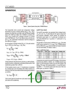
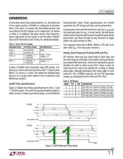
Figure 1. Typical System Using Two LTC6820 Devices
The transmitter drive current and comparator voltage
threshold are set by a resistor divider (R = R + R )
isoSPI Pulse Detail
The isoSPI transmitter can generate three voltage levels:
+V , 0V, and –V . To eliminate the DC signal component
BIAS
B1
B2
between the IBIAS pin and GND, with the divided voltage
A
A
tied to the ICMP pin. When the LTC6820 is enabled (not
and enhance reliability, isoSPI pulses are defined as
IDLE), I
is held at 2V, causing a current, I , to flow
B
BIAS
symmetric pulse pairs. A +1 pulse pair is defined as a
out of the IBIAS pin. The IP and IM pin drive currents are
+V pulse followed by a –V pulse. A –1 pulse pair is –V
A
A
A
20 • I . The comparator threshold is half the voltage on
B
followed by +V .
A
the ICMP pin (V
).
ICMP
The duration of each pulse is defined as t
. (The total
1/2PW
As an example, if divider resistor R is 1.21k and resistor
B1
isoSPI pulse duration is 2 • t
). The LTC6820 allows
1/2PW
R
is 787Ω (so that R
= 2k), then:
B2
BIAS
for two different t
values so that four types of pulses
1/2PW
2V
RB1+RB2
can be transmitted, as listed in Table 1.
IB =
=1mA
Table 1. isoSPI Pulse Types
PULSE TYPE
FIRST LEVEL
SECOND LEVEL ENDING LEVEL
I
= I = I = 20 • I = 20mA
DRV
IP
IM
B
Long +1
+V (150ns)
A
–V (150ns)
0V
0V
0V
0V
A
RB2
RB1+RB2
Long –1
–V (150ns)
A
+V (150ns)
A
V
ICMP = 2V •
=IB •RB2 = 788mV
Short +1
Short –1
+V (50ns)
A
–V (50ns)
A
–V (50ns)
A
+V (50ns)
A
V
= 0.5 • V = 394mV
TCMP
ICMP
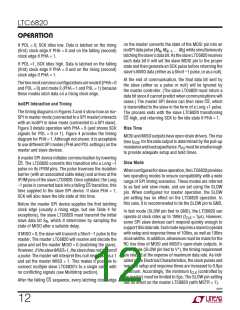
LongpulsesareusedtotransmitCSchanges.Shortpulses
transmit data (MOSI or MISO). An LTC6820 detects four
types of communication events from the SPI master: CS
falling, CS rising, SCK latching MOSI = 0, and SCK latch-
ing MOSI = 1. It converts each event into one of the four
pulse types, as shown in Table 2.
In this example, the pulse drive current I
andthereceivercomparatorswilldetectpulseswithIP-IM
amplitudes greater than 394mV.
will be 20mA,
DRV
If the isolation barrier uses 1:1 transformers connected
by a twisted pair and terminated with 100Ω resistors on
eachend,thenthetransmitteddifferentialsignalamplitude
( ) will be:
Table 2. Master Communication Events
SPI MASTER EVENT
TRANSMITTED PULSE
CS Rising
Long +1
RM
2
VA =IDRV
•
=1V
CS Falling
Long –1
SCK Latching Edge, MOSI = 1
SCK Latching Edge, MOSI = 0
Short +1
Short –1
(This result ignores transformer and cable losses, which
will reduce the amplitude).
6820f
10

 Linear [ Linear ]