LTC5588-1
APPLICATIONS INFORMATION
The LTC5588-1 is recommended for basestation applica-
tions using various modulation formats. Figure 14 shows
a typical application. The LTC2630 can be used to drive
the LINOPT pin via a SPI interface. At 3.3V supply, the
maximum LINOPT voltage is about 3.125V. Using an extra
buffer like the LTC6246 in unity-gain configuration can
increase the maximum LINOPT voltage to about 3.17V.
An LTC2630 with a 5V supply can drive the full 2V to 3.7V
range for the LINOPT pin.
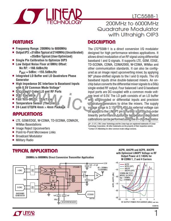
Figure12showstheACPR,AltCPRandACPR,AltCPRwith
OptimizedLINOPTvoltagevsRFOutputPowerat2.14GHz
for W-CDMA 1, 2 and 4 Carriers. A 4-Carriers W-CDMA
spectrum is shown in Figure 13 with and without LINOPT
voltage optimization.
–40
ACPR
4C
2C
ACPR (OPT)
1C
AltCPR
–50
AltCPR (OPT)
DOWNLINK TEST
MODEL 64 DPCH
–60
f
BB
f
LO
= 140MHz,
= 2280MHz
–70
–80
–90
–20
–15
–10
–5
0
5
55881 TA
RF OUTPUT POWER PER CARRIER (dBm)
Figure 12. ACPR, AltCPR and ACPR, AltCPR with Optimized LINOPT
Voltage vs RF Output Power at 2.14GHz for W-CDMA 1, 2 and 4 Carriers
–20
DOWNLINK TEST MODEL 64 DPCH
–40
–60
–80
f
f
= 140MHz
BB
LO
–100
–120
= 2280MHz
OPTIMIZED
NOT OPTIMIZED
2.115
2.125
2.135
2.145
2.155
2.165
RF FREQUENCY (GHz)
55881 F13
Figure 13. 4-Carrier W-CDMA Spectrum with and without LINOPT
Voltage Optimization
55881fb
27

 Linear [ Linear ]