LTC4270/LTC4271
PIN FUNCTIONS
CPD (Pin 8): Clock Transceiver Positive Input Output
(Digital). Connect to CPA through a data transformer.
See Applications Information for more information.
SDAIN (Pin 17): Serial Data Input. High impedance data
2
CND (Pin 9): Clock Transceiver Negative Input Output
(Digital). Connect to CNA through a data transformer.
inputfortheI Cserialinterfacebus.TheLTC4271usestwo
pinstoimplementthebidirectionalSDAfunctiontosimplify
2
optoisolation of the I C bus. To implement a standard
DPD (Pin 10): Data Transceiver Positive Input Output
(Digital). Connect to DPA through a data transformer.
bidirectional SDA pin, tie SDAOUT and SDAIN together.
See Applications Information for more information.
DND (Pin 11): Data Transceiver Negative Input Output
(Digital). Connect to DNA through a data transformer.
SCL (Pin 18): Serial Clock Input. High impedance clock
2
input for the I C serial interface bus. The SCL pin should
2
V
(Pins 12, 20): V IO Power Supply. Connect to
DD
be connected directly to the I C SCL bus line. SCL must
DD33
2
a 3.3V power supply relative to DGND. V
must be
be tied high if the I C serial interface bus is not used.
DD33
bypassed to DGND near the LTC4271 with at least a 0.1ꢀF
capacitor.
CAP1(Pin19):CorePowerSupplyBypassCapacitor.Con-
nect a 1μF Bypass capacitance to DGND for the internal
1.8V regulator. Do not use other capacitor values.
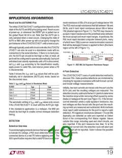
RESET(Pin14):ResetInput,ActiveLow.WhentheRESET
pin is low, the LTC4270/LTC4271 is held inactive with all
ports off and all internal registers reset to their power-up
states. When RESET is pulled high, the LTC4271 begins
normal operation. RESET can be connected to an exter-
nal capacitor or RC network to provide a power turn-on
delay. Internal filtering of the RESET pin prevents glitches
less than 1ꢀs wide from resetting the LTC4270/LTC4271.
AUTO (Pin 21): AUTO Pin Mode Input. AUTO pin mode
allows the LTC4271 to detect and power up a PD even if
2
there is no host controller present on the I C bus. The
AUTO pin determines the state of the internal registers
when the LTC4271 is reset or comes out of V UVLO
DD
(seeLTC4271SoftwareProgrammingdocumentation).The
states of these register bits can subsequently be changed
Internally pulled up to V .
DD
2
viatheI Cinterface.InternallypulleddowntoDGND.Must
INT(Pin15):InterruptOutput,OpenDrain.INTwillpulllow
whenanyoneofseveraleventsoccurintheLTC4271.Itwill
return to a high impedance state when bits 6 or 7 are set
in the Reset PB register (1Ah). The INT signal can be used
to generate an interrupt to the host processor, eliminating
the need for continuous software polling. Individual INT
events can be disabled using the INT Mask register (01h).
See LTC4271 Software Programming documentation for
more information. The INT pin is only updated between
be tied locally to either V or DGND.
DD
GP1 (Pin 22): General Purpose Digital Input Output for
customer applications. Referenced to DGND.
GP0 (Pin 23): General Purpose Digital Input Output for
customer applications. Referenced to DGND.
MSD(Pin24):MaskableShutdownInput.Activelow.When
pulled low, all ports that have their corresponding mask
bit set in the mconfig register (17h) will be reset. Internal
filtering of the MSD pin prevents glitches less than 1ꢀs
wide from resetting ports. The MSD Pin Mode register can
2
I C transactions.
SDAOUT (Pin 16): Serial Data Output, Open Drain Data
2
Output for the I C Serial Interface Bus. The LTC4271 uses
configuretheMSDpinpolarity. InternallypulleduptoV .
DD
two pins to implement the bidirectional SDA function to
DGND(ExposedPadPin25):DigitalGround.DGNDshould
2
simplify optoisolation of the I C bus. To implement a stan-
be connected to the return from the V supply.
DD
dardbidirectionalSDApin,tieSDAOUTandSDAINtogether.
42701f
15

 Linear [ Linear ]