LTC4270/LTC4271
APPLICATIONS INFORMATION
Reset and the AUTO/MID Pins
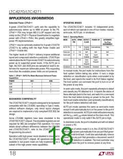
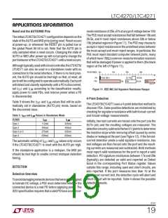
moderesistanceof25k 5%atanyportvoltagebelow10V.
ThePSEmustacceptresistancesthatfallbetween19kand
26.5k, and it must reject resistances above 33k or below
15k(shadedregionsinFigure11). ThePSEmaychooseto
acceptorrejectresistancesintheundefinedareasbetween
the must-accept and must-reject ranges. In particular, the
PSE must reject standard computer network ports, many
ofwhichhave150Ωcommon-modeterminationresistors
that will be damaged if power is applied to them (the black
region at the left of Figure 11).
TheinitialLTC4270/LTC4271configurationdependsonthe
state of the AUTO and MID pins during reset. Reset occurs
at power-up, or whenever the RESET pin is pulled low or
the global Reset All bit is set. Note that the AUTO pin is
only sampled when a reset occurs. Changing the state of
AUTO or MID after power-up will not properly change the
portbehavioroftheLTC4270/LTC4271untilaresetoccurs.
Althoughtypicallyusedwithahostcontroller,theLTC4270/
LTC4271 can also be used in a standalone mode with no
connection to the serial interface. If there is no host pres-
ent, the AUTO pin should be tied high so that, at reset, all
portswillbeconfiguredtooperateautomatically.Eachport
will detect and classify repeatedly until a PD is discovered,
RESISTANCE 0Ω
10k
20k
30k
150Ω (NIC)
23.75k
26.25k
26.5k
PD
PSE
15k 19k
33k
42701 F11
set I
and I
according to the classification results,
Figure 11. IEEE 802.3af Signature Resistance Ranges
CUT
LIM
apply power to valid PDs, and remove power when a PD
is disconnected.
4-Point Detection
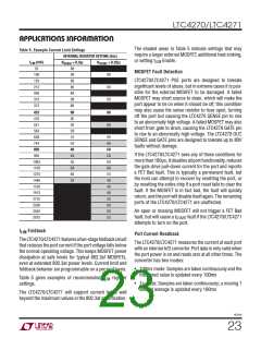
Table 3 shows the I
and I
values that will be auto-
LIM
CUT
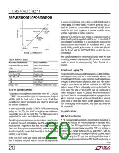
TheLTC4270/LTC4271usesa4-pointdetectionmethodto
discover PDs. False-positive detections are minimized by
checkingforsignatureresistancewithbothforced-current
and forced-voltage measurements.
matically set in standalone (AUTO pin) mode, based on
the discovered class.
Table 3. ICUT and ILIM Values in Standalone Mode
CLASS
Class 1
ICUT
ILIM
Initially, two test currents are forced onto the port (via the
OUTn pin) and the resulting voltages are measured. The
detectioncircuitrysubtractsthetwoV-Ipointstodetermine
the resistive slope while removing offset caused by series
diodes or leakage at the port (see Figure 12). If the forced-
current detection yields a valid signature resistance, two
test voltages are then forced onto the port and the result-
ing currents are measured and subtracted. Both methods
must report valid resistances for the port to report a valid
detection. PD signature resistances between 17k and 29k
(typically) are detected as valid and reported as Detect
Good in the corresponding Port Status register. Values
outside this range, including open and short circuits, are
also reported. If the port measures less than 1V at the
first forced-current test, the detection cycle will abort and
Short Circuit will be reported. Table 4 shows the possible
detection results.
112mA
206mA
375mA
638mA
425mA
425mA
425mA
850mA
Class 2
Class 3 or 0
Class 4
The automatic setting of I
and I values only occurs
LIM
CUT
if the LTC4270/LTC4271 is reset with the AUTO pin high.
If the standalone application is a midspan, the MID pin
should be tied high to enable correct midspan detection
timing.
DETECTION
Detection Overview
Toavoiddamagingnetworkdevicesthatwerenotdesigned
to tolerate DC voltage, a PSE must determine whether the
connected device is a real PD before applying power. The
IEEEspecificationrequiresthatavalidPDhaveacommon-
42701f
19

 Linear [ Linear ]