LTC3407
U
W U U
APPLICATIO S I FOR ATIO
capacitors, such as Sanyo POSCAP, offer very low ESR,
but have a lower capacitance density than other types.
Tantalumcapacitorshavethehighestcapacitancedensity,
but it has a larger ESR and it is critical that the capacitors
are surge tested for use in switching power supplies. An
excellent choice is the AVX TPS series of surface mount
tantalums, available in case heights ranging from 2mm to
4mm. Aluminum electrolytic capacitors have a signifi-
cantly larger ESR, and are often used in extremely cost-
sensitiveapplicationsprovidedthatconsiderationisgiven
to ripple current ratings and long term reliability. Ceramic
capacitorshavethelowestESRandcost, butalsohavethe
lowest capacitance density, a high voltage and tempera-
ture coefficient, and exhibit audible piezoelectric effects.
In addition, the high Q of ceramic capacitors along with
trace inductance can lead to significant ringing. Other
capacitor types include the Panasonic Special Polymer
(SP) capacitors.
Also, ceramic caps are prone to temperature effects which
requires the designer to check loop stability over the
operating temperature range. To minimize their large
temperature and voltage coefficients, only X5R or X7R
ceramic capacitors should be used. A good selection of
ceramic capacitors is available from Taiyo Yuden, TDK,
and Murata.
Great care must be taken when using only ceramic input
and output capacitors. When a ceramic capacitor is used
at the input and the power is being supplied through long
wires,suchasfromawalladapter,aloadstepattheoutput
can induce ringing at the VIN pin. At best, this ringing can
couple to the output and be mistaken as loop instability. At
worst, the ringing at the input can be large enough to
damage the part.
Since the ESR of a ceramic capacitor is so low, the input
and output capacitor must instead fulfill a charge storage
requirement.Duringaloadstep,theoutputcapacitormust
instantaneously supply the current to support the load
untilthefeedbackloopraisestheswitchcurrentenoughto
support the load. The time required for the feedback loop
to respond is dependent on the compensation and the
output capacitor size. Typically, 3-4 cycles are required to
respond to a load step, but only in the first cycle does the
output drop linearly. The output droop, VDROOP, is usually
about3timesthelineardropofthefirstcycle.Thus,agood
place to start is with the output capacitor size of approxi-
mately:
In most cases, 0.1µF to 1µF of ceramic capacitors should
also be placed close to the LTC3407 in parallel with the
main capacitors for high frequency decoupling.
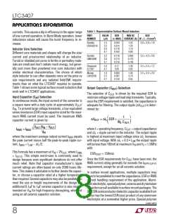
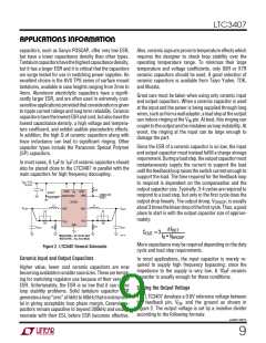
V = 2.5V
IN
TO 5.5V
C
IN
R5
RUN2
V
RUN1
POR
IN
BURST*
POWER-ON
RESET
MODE/SYNC
PULSESKIP*
LTC3407
L1
L2
V
OUT2
SW2
SW1
V
OUT1
C5
R4
C4
R2
V
FB1
V
FB2
GND
R1
C
OUT1
C
R3
OUT2
∆IOUT
COUT ≈ 3
3407 F02
*MODE/SYNC = 0V: PULSE SKIP
MODE/SYNC = V : Burst Mode
fO • VDROOP
IN
More capacitance may be required depending on the duty
cycle and load step requirements.
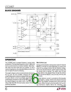
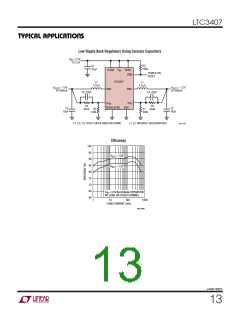
Figure 2. LTC3407 General Schematic
Ceramic Input and Output Capacitors
In most applications, the input capacitor is merely re-
quired to supply high frequency bypassing, since the
impedance to the supply is very low. A 10µF ceramic
capacitor is usually enough for these conditions.
Higher value, lower cost ceramic capacitors are now
becomingavailableinsmallercasesizes.Thesearetempt-
ing for switching regulator use because of their very low
ESR. Unfortunately, the ESR is so low that it can cause
loop stability problems. Solid tantalum capacitor ESR
generatesaloop“zero”at5kHzto50kHzthatisinstrumen-
tal in giving acceptable loop phase margin. Ceramic ca-
pacitors remain capacitive to beyond 300kHz and usually
resonate with their ESL before ESR becomes effective.
Setting the Output Voltage
The LTC3407 develops a 0.6V reference voltage between
the feedback pin, VFB, and the ground as shown in
Figure 2. The output voltage is set by a resistive divider
according to the following formula:
sn3407 3407fs
9

 Linear [ Linear ]