LTC3407
U
W U U
APPLICATIO S I FOR ATIO
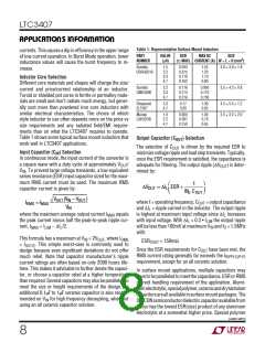
Table 1. Representative Surface Mount Inductors
currents. This causes a dip in efficiency in the upper range
of low current operation. In Burst Mode operation, lower
inductance values will cause the burst frequency to in-
crease.
PART
NUMBER
VALUE
(µH)
DCR
MAX DC
SIZE
3
(Ω MAX) CURRENT (A) W × L × H (mm )
Sumida
CDRH3D16
1.5
2.2
3.3
4.7
0.043
0.075
0.110
0.162
1.55
1.20
1.10
0.90
3.8 × 3.8 × 1.8
Inductor Core Selection
Different core materials and shapes will change the size/
current and price/current relationship of an inductor.
Toroid or shielded pot cores in ferrite or permalloy mate-
rials are small and don’t radiate much energy, but gener-
ally cost more than powdered iron core inductors with
similar electrical characterisitics. The choice of which
style inductor to use often depends more on the price vs
size requirements and any radiated field/EMI require-
ments than on what the LTC3407 requires to operate.
Table 1 shows some typical surface mount inductors that
work well in LTC3407 applications.
Sumida
CMD4D06
2.2
3.3
4.7
0.116
0.174
0.216
0.950
0.770
0.750
3.5 × 4.3 × 0.8
Panasonic
ELT5KT
3.3
4.7
0.17
0.20
1.00
0.95
4.5 × 5.4 × 1.2
2.5 × 3.2 × 2.0
Murata
LQH32CN
1.0
2.2
4.7
0.060
0.097
0.150
1.00
0.79
0.65
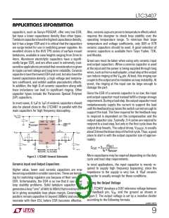
Output Capacitor (COUT) Selection
The selection of COUT is driven by the required ESR to
minimizevoltagerippleandloadsteptransients.Typically,
once the ESR requirement is satisfied, the capacitance is
adequate for filtering. The output ripple (∆VOUT) is deter-
mined by:
Input Capacitor (CIN) Selection
In continuous mode, the input current of the converter is
a square wave with a duty cycle of approximately VOUT
/
VIN. To prevent large voltage transients, a low equivalent
series resistance (ESR) input capacitor sized for the maxi-
mum RMS current must be used. The maximum RMS
capacitor current is given by:
⎛
⎞
1
∆VOUT ≈ ∆IL ESR +
⎜
⎟
8fO COUT
⎝
⎠
VOUT (V – VOUT
)
IN
where f = operating frequency, COUT = output capacitance
and ∆IL = ripple current in the inductor. The output ripple
is highest at maximum input voltage since ∆IL increases
with input voltage. With ∆IL = 0.3 • ILIM the output ripple
will be less than 100mV at maximum VIN and fO = 1.5MHz
with:
IRMS ≈ IMAX
V
IN
where the maximum average output current IMAX equals
the peak current minus half the peak-to-peak ripple cur-
rent, IMAX = ILIM – ∆IL/2.
This formula has a maximum at VIN = 2VOUT, where IRMS
= IOUT/2. This simple worst-case is commonly used to
design because even significant deviations do not offer
much relief. Note that capacitor manufacturer’s ripple
current ratings are often based on only 2000 hours life-
time. This makes it advisable to further derate the capaci-
tor, or choose a capacitor rated at a higher temperature
thanrequired. Severalcapacitorsmayalsobeparalleledto
meet the size or height requirements of the design. An
additional 0.1µF to 1µF ceramic capacitor is also recom-
mended on VIN for high frequency decoupling, when not
using an all ceramic capacitor solution.
ESRCOUT < 150mΩ
Once the ESR requirements for COUT have been met, the
RMS current rating generally far exceeds the IRIPPLE(P-P)
requirement, except for an all ceramic solution.
In surface mount applications, multiple capacitors may
have to be paralleled to meet the capacitance, ESR or RMS
current handling requirement of the application. Alumi-
numelectrolytic,specialpolymer,ceramicanddrytantulum
capacitorsareallavailableinsurfacemountpackages.The
OS-CONsemiconductordielectriccapacitoravailablefrom
Sanyo has the lowest ESR(size) product of any aluminum
electrolytic at a somewhat higher price. Special polymer
sn3407 3407fs
8

 Linear [ Linear ]