LTC3101
OPERATION
remainenabled. Power-downisusuallyaccomplishedby
having the microprocessor monitor PBSTAT to detect an
additional push of the pushbutton. Once this is detected,
the microprocessor disables the LTC3101 by forcing
PWRON low (or simply releasing PWRON and allowing
it be pulled low by its internal pull-down resistor). In
this manner, a single external momentary pushbutton is
all that is required to provide sequenced power-up and
power-down control.
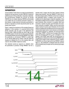
duration that is longer than the 24ms (typical) internal
debouncing duration. Once the PWRKEY is held low for
the debouncing duration, PBSTAT is driven low to indicate
the pushbutton status. In addition, buck converter 1 is
enabled and its output begins rising into regulation. Once
thefeedbackvoltageofbuckconverter1reachesitspower
good threshold, buck converter 2 is enabled. After buck
converter 2 reaches its power good threshold, the buck-
boost converter is enabled. Finally, once the buck-boost
output reaches its power good threshold, the Hot Swap
output is enabled and simultaneously the microprocessor
resetdurationbeginswhena1μA(nominal)currentbegins
Figure 1 depicts the waveforms in the standard power-up
sequence. In this example, it is assumed that all three
DC/DC converter rails are used in the application and
therefore ENA1, ENA2 and ENA3 are driven high (or tied
totheMAXoutput).Anexternalnormally-openpushbutton
is connected between ground and the PWRKEY pin. When
the pushbutton is not pressed, PWRKEY is pulled high
via an internal 400k pull-up resistor. Until the power-up
sequence is initiated, the IC is in the standby state, and
only the LDO and MAX outputs are active.
charging the external C capacitor. The microprocessor
RS
reset output, RESET, is driven low throughout this entire
power-up sequence until the C pin is charged to 1.2V
RS
(typical). Once RESET goes high, the microprocessor in
the application initializes and must drive the PWRON input
of the LTC3101 high in order to keep the LTC3101 enabled.
If PWRON is not driven high by the time PWRKEY returns
high (i.e., the pushbutton is released) then the LTC3101
will be disabled and all outputs will be actively discharged
to ground.
The standard power-up sequence is initiated when
the pushbutton is pressed, forcing PWRKEY low for a
PWRKEY
PBSTAT
24ms BLANKING
V
V
BUCK 1
BUCK 2
OUT
OUT
V
OUT
BUCK-BOOST
HSO
C
RS
RESET
PWRON
3101 F01
Figure 1. Power-Up Sequence Waveforms
3101f
14

 Linear [ Linear ]