LTC2943
APPLICATIONS INFORMATION
Example 1: a register value of O[7:0] = A8h P[7:0] = 40h
The actual temperature can be obtained from the two byte
register U[7:0]V[7:0] by:
togetherwithasenseresistorR
to a battery current:
=±0mΩcorresponds
SENSE
RESULTh
FFFFh
RESULTDEC
6±±3±
T=±10K •
=±10K •
60mV A840h –7FFF
h
=
IBAT
=
•
50mΩ
7FFFh
Example: a register value of U[7:0] = 96h, V[7:0] = 96h
corresponds to ~300K or ~27°C
60mV 43072–32767
•
≈377.3mA
50mΩ
32767
Ahightemperaturelimitof60°Cisprogrammedbysetting
register W to A7h. Note that the temperature threshold
register is a single byte register and only the eight MSBs
of the 11 bits temperature result are checked.
The positive current result indicates that the battery is
being charged.
The values in the threshold register for the current mode
Q,R,S,T are also expressed in excess –32767 representa-
tion in the same manner as the current conversion result.
The alert after a current measurement is set if the result
is higher than the value stored in the high threshold reg-
isters Q,R or lower than the value stored in the low value
registers S,T.
Effect of Differential Offset Voltage on Total Charge
Error
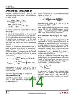
In battery gas gauges, an important parameter is the
differential offset (V ) of the circuitry monitoring the
OS
battery charge. Many coulomb counter devices perform
an analog to digital conversion of V
, where V
SENSE
SENSE
Example 2: In an application, the user wants to get an
alert if the absolute current through the sense resistor,
is the voltage drop across the sense resistor, and ac-
cumulate the conversion results to infer charge. In such
an architecture, the differential offset V causes relative
OS
R
, of ±0mΩ exceeds 1A. This is achieved by setting
SENSE
the upper threshold I
in register [Q,R] to 1A and the
charge error of V /V
. For small V
values V
SENSE OS
HIGH
OS SENSE
can be the main source of error.
lower threshold I
for I leads to:
in register [S,T] to –1A. The formula
LOW
BAT
The LTC2943 performs the tracking of the charge with an
analog integrator. This approach allows to continuously
monitor the battery charge and significantly lowers the
error due to differential offset. The relative charge error
1A •50mΩ
IHIGH(DEC)=
•32767+32767=60073
60mV
–1A •50mΩ
due to offset (CE ) can be expressed by:
ILOW(DEC)
=
•32767 +32767=5461
OV
60mV
2
VOS
CEOV
=
Leading the user to set Q[7:0] = EAh, R[7:0] = A9h for
the high threshold and S[7:0] = 1±h and T[7:0] = ±±h for
the low threshold.
V
SENSE
As example, at a 1mV input signal, a differential voltage
offset V = 20µV results in a 2% error using digital
OS
Temperature Registers (U,V), and Temperature
Threshold Registers (W,X)
integration, whereas the error is only 0.04% (a factor of
±0 times smaller!) using the analog integration approach
of LTC2943.
As the ADC resolution is 11 bits in temperature mode, the
lowest five bits of the combined temperature registers
(U, V) are always zero.
2943fa
14
For more information www.linear.com/LTC2943

 Linear [ Linear ]