LTC2943
APPLICATIONS INFORMATION
To use as much of the range of the accumulated charge
register as possible the prescaler factor M should be
the control register. At power-up, bits B[7:6] are set to
[00] and the ADC is in sleep mode.
chosen for a given battery capacity Q
and a sense
BAT
A single conversion of the three measured quantities
is initiated by setting the bit B[7:6] to [01]. After three
conversions (voltage, current and temperature), the ADC
resets B[7:6] to [00] and goes back to sleep.
resistor R
as:
SENSE
QBAT
216 •0.340mAh
RSENSE
±0mΩ
M≥4096•
•
The LTC2943 is set to scan mode by setting B[7:6] to
[10]. In scan mode the ADC converts voltage, current,
then temperature, then sleeps for approximately 10 sec-
onds. It then reawakens automatically and repeats the
three conversions. The chip remains in scan mode until
reprogrammed by the host.
M can be set to 1, 4, 16, ... 4096 by programming B[±:3]
of the control register as M = 2
The default value is 4096.
2•(4 • B[±] + 2 • B[4] + B[3])
.
In the above example of a 100mAh battery and an R
SENSE
of ±0mΩ, the prescaler should be programmed to
M=64.Theq isthen±.313μAhandthebatterycapacity
LSB
Programming B[7:6] to [11] sets the chip into automatic
mode where the ADC continuously performs voltage,
current and temperature conversions. The chip stays in
automatic mode until reprogrammed by the host.
corresponds to roughly 18821 q s.
LSB
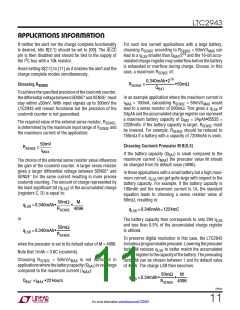
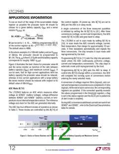
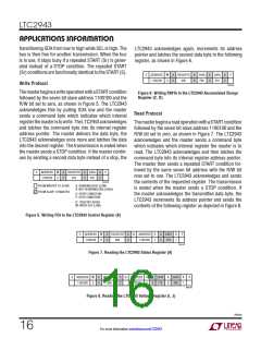
Figure 3 illustrates the best choice for prescaler value M
and the sense resistor as function of the ratio between
battery capacity (Q ) and maximum current (I
). It
BAT
MAX
Programming B[7:6] to [00] puts the ADC to sleep. If
control bits B[7:6] change within a conversion, the ADC
will complete the running cycle of conversions before
entering the newly selected mode.
can be seen, that for high current applications with low
battery capacity the prescaler value should be reduced,
whereas in low current applications with a large battery
the sense resistor should be reduced with respect to its
A conversion of voltage requires 33ms (typical), and cur-
rentandtemperatureconversionsarecompletedin4.±ms
(typical).Attheendofeachconversion,thecorresponding
registers are updated. If the converted quantity exceeds
the values programmed in the threshold registers, a flag
is set in the status register and the ALCC pin is pulled low
(if alert mode is enabled).
default value of ±0mV/I
.
MAX
ADC Mode B[7:6]
The LTC2943 features an ADC which measures either
–
voltage on SENSE (battery voltage), voltage difference
+
–
between SENSE and SENSE (battery current) or tem-
peratureviaaninternaltemperaturesensor. Thereference
voltage and clock for the ADC are generated internally.
DuringADCconversionsadditionalcurrentsaresunkfrom
+
–
SENSE andSENSE ,refertotheElectricalCharacteristics
table for details.
The ADC has four different modes of operation as shown
in Table 3. These modes are controlled by bits B[7:6] of
16
50mV
0.34mAh • 2
R
SENSE
≤
R
SENSE
≤
• 50mΩ
I
Q
BAT
MAX
M = 1
M = 4
M = 16
M = 64
M = 256
M = 1024
M = 4096
0.005h
0.02h
0.08h
0.34h
1.4h
5.5h
22h
Q
/I
BAT MAX
2943 F03
Figure 3. Choice of Sense Resistor and Prescaler as Function of Battery Capacity and Maximum Current
2943fa
12
For more information www.linear.com/LTC2943

 Linear [ Linear ]