LTC1733
W U U
APPLICATIO S I FOR ATIO
U
Stability
105°C – 55°C
(5V – 3.75V)•40°C / W 50°C /A
50°C
IBAT
=
=
= 1A
The constant-voltage mode feedback loop is stable
without any compensation when a battery is connected.
However, a 1µF capacitor with a 1Ω series resistor to GND
is recommended at the BAT pin to keep ripple voltage low
when the battery is disconnected.
Furthermore, the voltage at the PROG pin will change
proportionally with the charge current as discussed in the
Programming Charge Current section.
It is important to remember that LTC1733 applications do
notneedtobedesignedforworst-casethermalconditions
since the IC will automatically reduce power dissipation
when the junction temperature reaches approximately
105°C. See Design Note 283 for additional information.
In the constant-current mode it is the PROG pin that is in
the feedback loop and not the battery. The constant-
current mode stability is affected by the impedance at the
PROG pin. With no additional capacitance on the PROG
pin, stability is acceptable with program resistor values as
high as 50k. However, additional capacitance on this node
reduces the maximum allowed program resistor. The pole
frequency at the PROG pin should be kept above 500kHz.
Therefore, if the PROG pin is loaded with a capacitance, C,
the following equation should be used to calculate the
Board Layout Considerations
In order to be able to deliver maximum charge current
under all conditions, it is critical that the exposed pad on
the backside of the LTC1733 package is soldered to the
board. Correctly soldered to a 2500mm2 double-sided
1oz. copper board the LTC1733 has a thermal resistance
of approximately 40°C/W. Failure to make thermal contact
between the exposed pad on the backside of the package
and the copper board will result in thermal resistances far
greater than 40°C/W. As an example, a correctly soldered
LTC1733 can deliver over 1250mA to a battery from a 5V
supply at room temperature. Without a backside thermal
connection, this number could drop to less than 500mA.
maximum resistance value for RPROG
:
RPROG < 1/(6.283 • 500E3 • C)
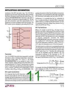
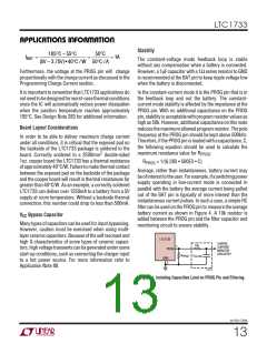
Average, rather than instantaneous, battery current may
beofinteresttotheuser.Forexample,ifaswitchingpower
supply operating in low-current mode is connected in
parallel with the battery the average current being pulled
out of the BAT pin is typically of more interest than the
instantaneous current pulses. In such a case, a simple RC
filter can be used on the PROG pin to measure the average
battery current as shown in Figure 4. A 10k resistor is
added between the PROG pin and the filter capacitor and
monitoring circuit to ensure stability.
VCC Bypass Capacitor
Many types of capacitors can be used for input bypassing.
However, caution must be exercised when using multi-
layer ceramic capacitors. Because of the self resonant and
high Q characteristics of some types of ceramic capaci-
tors, high voltage transients can be generated under some
start-up conditions, such as connecting the charger input
to a hot power source. For more information refer to
Application Note 88.
LTC1733
CHARGE
10k
7
CURRENT
MONITOR
CIRCUITRY
PROG
GND
R
PROG
C
FILTER
5
1733 F04
Figure 4. Isolating Capacitive Load on PROG Pin and Filtering.
sn1733 1733fs
13

 Linear [ Linear ]