LTC1733
W U U
U
APPLICATIO S I FOR ATIO
Ifathermistorwithatolerancelessthan±10%isused, the
trip point errors begin to depend on errors other than
thermistor tolerance including the input offset voltage of
theinternalcomparatorsoftheLTC1733andtheeffectsof
internal voltage drops due to high charging currents.
105°C. As the battery voltage rises, the LTC1733 either
returns to constant-current mode or it enters constant-
voltage mode straight from constant-temperature mode.
Regardless of mode, the voltage at the PROG pin is
proportional to the current being delivered to the battery.
Constant-Current/Constant-Voltage/
Constant-Temperature
Power Dissipation
The conditions that cause the LTC1733 to reduce charge
current due to the thermal protection feedback can be
approximated by considering the power dissipated in the
IC. For high charge currents, the LTC1733 power dissipa-
tion is approximately:
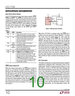
The LTC1733 uses a unique architecture to charge a
battery in a constant-current, constant-voltage, constant-
temperature fashion. Figure 1 shows a simplified block
diagram of the LTC1733. Three of the amplifier feedback
loops shown control the constant-current, CA, constant-
voltage, VA, and constant-temperature, TA modes. A
fourth amplifier feedback loop, MA, is used to increase the
output impedance of the current source pair, M1 and M2
(note that M1 is the internal P-channel power MOSFET). It
ensures that the drain current of M1 is exactly 1000 times
greater than the drain current of M2.
PD = (VCC – VBAT) • IBAT
where PD is the power dissipated, VCC is the input supply
voltage, VBAT is the battery voltage, and IBAT is the battery
charge current. It is not necessary to perform any worst-
case power dissipation scenarios because the LTC1733
will automatically reduce the charge current to maintain
the die temperature at approximately 105°C. However, the
approximate ambient temperature at which the thermal
feedback begins to protect the IC is:
Amplifiers CA, TA, and VA are used in three separate
feedback loops to force the charger into constant-current,
temperature, or voltage mode, respectively. Diodes, D1,
D2, and D3 provide priority to whichever loop is trying to
reduce the charging current the most. The outputs of the
other two amplifiers saturate low which effectively re-
moves their loops from the system. When in constant-
current mode, CA servos the voltage at the PROG pin to be
precisely 1.50V (or 0.15V when in trickle-charge mode).
TA limits the die temperature to approximately 105°C
when in constant-temperature mode and the PROG pin
voltage gives an indication of the charge current as dis-
cussed in “Programming Charge Current” . VA servos its
inverting input to precisely 2.485V when in constant-
voltage mode and the internal resistor divider made up of
R1 and R2 ensures that the battery voltage is maintained
at either 4.1V or 4.2V. Again, the PROG pin voltage gives
an indication of the charge current.
TA = 105°C – PDθJA
TA = 105°C – (VCC – VBAT) • IBAT • θJA
Example: Consider an LTC1733 operating from a 5V wall
adapter providing 1.2A to a 3.75V Li-Ion battery. The
ambient temperature above which the LTC1733 will begin
to reduce the 1.2A charge current is approximately:
TA = 105°C – (5V – 3.75V) • 1.2A • 40°C/W
TA = 105°C – 1.5W • 40°C/W = 105°C – 60°C = 45°C
The LTC1733 can be used above 45°C, but the charge
current will be reduced below 1.2A. The approximate
charge current at a given ambient temperature can be
approximated by:
105°C – TA
(VCC – VBAT )•θJA
In typical operation, the charge cycle begins in constant-
current mode with the current delivered to the battery
equal to 1500V/RPROG. If the power dissipation of the
LTC1733 results in the junction temperature approaching
105°C, the amplifier (TA) will begin decreasing the charge
current to limit the die temperature to approximately
IBAT
=
Consider the above example with an ambient temperature
of 55°C. The charge current will be reduced to approxi-
mately:
sn1733 1733fs
12

 Linear [ Linear ]