LTC1733
W U U
U
APPLICATIO S I FOR ATIO
+
Open-Drain Status Outputs
V
DD
V
8
The LTC1733 has three open-drain status outputs: ACPR,
CHRG and FAULT. The ACPR pin pulls low when an input
voltage greater than the undervoltage lockout threshold is
applied and goes high impedance when power (VIN < VUV)
is removed. CHRG and FAULT work together to indicate
the status of the charge cycle. Table 1 describes the status
of the charge cycle based on the CHRG and FAULT
outputs.
V
CC
400k
µPROCESSOR
LTC1733
2k
3
OUT
IN
CHRG
1733 F02
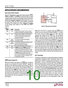
Figure 2. Microprocessor Interface
Table 1.
FAULT
CHRG
Description
When the LTC1733 is in charge mode, the CHRG pin is
pulled low by the internal N-channel MOSFET. To detect
this mode, force the digital output pin, OUT, high and
measure the voltage at the CHRG pin. The N-channel
MOSFET will pull the pin low even with the 2k pull-up
resistor. Once the charge current drops to 10% of the full-
scale current (C/10), the N-channel MOSFET is turned off
and a 25µA current source is connected to the CHRG pin.
The IN pin will then be pulled high by the 2k pull-up. By
forcing the OUT pin to a high impedance state, the current
source will pull the pin low through the 400k resistor.
When the internal timer has expired, the CHRG pin will
assume a high impedance state and the 400k resistor will
then pull the pin high to indicate that charging has termi-
nated.
High
Low
Charge cycle has started, C/10 has not been
reached and charging is proceeding normally.
Low
Low
Charge cycle has started, C/10 has not been
reached, but the charge current and timer
have been paused due to an NTC out-of-
temperature condition.
High
Low
25µA
C/10 has been reached and charging is
pulldown proceeding normally.
25µA
C/10 has been reached but the charge current
pulldown and timer have paused due to an
NTC out-of-temperature condition.
High
Low
High
High
Normal timeout (charging has terminated).
If FAULT goes low and CHRG goes high
impedance simultaneously, then the LTC1733
has timed out due to a bad cell (V
after one-quarter the programmed charge time).
If CHRG goes high impedance first, then
the LTC1733 has timed out normally (charging
has terminated), but NTC is indicating an out-
of-temperature condition.
<2.48V
BAT
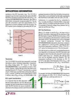
NTC Thermistor
Thebatterytemperatureismeasuredbyplacinganegative
temperature coefficient (NTC) thermistor close to the
batterypack.TheNTCcircuitryisshowninFigure3.Touse
this feature, connect a 10k NTC thermistor between the
NTCpinandgroundandaresistor(RHOT)fromtheNTCpin
to VCC. RHOT should be a 1% resistor with a value equal to
the value of the chosen NTC thermistor at 50°C (this value
is 4.1k for a Vishay NTHS0603N02N1002J thermistor).
The LTC1733 goes into hold mode when the resistance of
the NTC thermistor drops below 4.1k which should be
at 50°C. The hold mode freezes the timer and stops
the charge cycle until the thermistor indicates a return
to a valid temperature. As the temperature drops, the
CHRG Status Output Pin
When the charge cycle starts, the CHRG pin is pulled to
ground by an internal N-channel MOSFET capable of
driving an LED. When the charge current drops to 10% of
the full-scale current (C/10), the N-channel MOSFET is
latched off and a weak 25µA current source to ground is
connected to the CHRG pin. After a time-out occurs, the
pin assumes a high impedance state. By using two differ-
ent value pull-up resistors a microprocessor can detect
three states from this pin (charging, C/10, and time-out).
See Figure 2.
sn1733 1733fs
10

 Linear [ Linear ]