LTC1733
W U U
APPLICATIO S I FOR ATIO
U
resistance of the NTC thermistor rises. The LTC1733 is
designed to go into hold mode when the value of the NTC
thermistor increases to seven times the value of RHOT. For
a Vishay NTHS0603N02N1002J thermistor, this value is
28.2k which corresponds to approximately 0°C. The hot
and cold comparators each have approximately 2°C of
hysteresis to prevent oscillation about the trip point. The
NTC function can be disabled by grounding the NTC pin.
package temperature rather than the battery temperature.
This problem can be eliminated by thermally coupling the
NTC thermistor to the battery and not to the LTC1733.
Furthermore, it is essential that the VCC connection to
RHOT is made according to standard Kelvin sense tech-
niques. Since VCC is a high current path into the LTC1733,
it is essential to minimize voltage drops between the VCC
input pin and the top of RHOT
.
V
CC
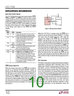
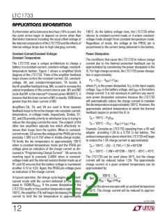
NTC Trip Point Errors
7/8 V
–
+
CC
CC
CC
When a 1% resistor is used for RHOT, the major error in
the 50°C trip point is determined by the tolerance of the
NTC thermistor. A typical 10k NTC thermistor has a ±10%
tolerance. By looking up the temperature coefficient of the
thermistor at 50°C, the tolerance error can be calculated
in degrees centigrade. Consider the Vishay
NTHS0603N02N1002J thermistor which has a tempera-
ture coefficient of –3.3%/°C at 50°C. Dividing the toler-
ance by the temperature coefficient, ±10%/(–3.3%/°C) =
±3°C, gives the temperature error of the hot trip point.
R
HOT
1%
TOO COLD
TOO HOT
NTC
1/2 V
R
+
–
NTC
10k
3/160 V
+
–
DISABLE NTC
The cold trip point is a little more complicated because its
error depends on the tolerance of the NTC thermistor and
thedegreetowhichtheratioofitsvalueat0°Canditsvalue
at 50°C varies from 7 to 1. Therefore, the cold trip point
error can be calculated using the tolerance, TOL, the
temperature coefficient of the thermistor at 0°C, TC
(in %/°C), the value of the thermistor at 0°C, RCOLD, and
the value of the thermistor at 50°C, RHOT. The formula is:
LTC1733
1733 F03
Figure 3.
Thermistors
The LTC1733 NTC trip points were designed to work with
thermistors whose resistance-temperature characteris-
tics follow Vishay Dale’s “R-T Curve 2”. The Vishay
NTHS0603N02N1002J is an example of such a ther-
mistor. However, Vishay Dale has many thermistor prod-
uctsthatfollowthe“R-TCurve2”characteristicinavariety
of sizes. Futhermore, any thermistor whose ratio of RCOLD
to RHOT is about 7.0 will also work (Vishay Dale R-T Curve
2 shows a ratio of RCOLD to RHOT of 2.816/0.4086 = 6.9).
1+ TOL RCOLD
•
– 1 •100
7
RHOT
TC
TemperatureError(°C)=
Forexample,theVishayNTHS0603N02N1002Jthermistor
with a tolerance of ±10%, TC of –4.5%/°C, and RCOLD
RHOT of 6.89, has a cold trip point error of:
/
NTC Layout Considerations
1± 0.10
It is important that the NTC thermistor not be in close
thermal contact with the LTC1733. Because the LTC1733
package can reach temperatures in excess of the 50°C trip
point, the NTC function can cause a hysteretic oscillation
which turns the charge current on and off according to the
•6.89 – 1 •100
7
Temperature Error (°C) =
–4.5
= –1.8°C, +2.5°C
sn1733 1733fs
11

 Linear [ Linear ]