LTC1559-3.3/LTC1559-5
U
W U U
APPLICATIONS INFORMATION
example, a small 60mAhr SAFT cell can back up the
systemfor20minutesatanoutputpowerof100mW.Note
that at VCC = 3.07V (LTC1559-3.3), the boost converter
efficiencyimprovesandallowsmorebackuptimefromthe
same cell compared to VCC = 4.625V (LTC1559-5).
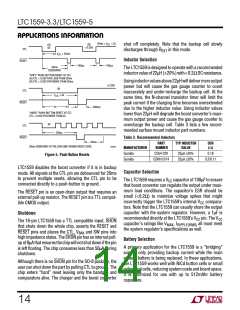
CTL pin. In trickle charge mode, CTL is regulated to 0.5V,
resulting in a CTL pin current of (VBAT – 0.5)/REXT. This
current is internally multiplied to feed back ten times the
R
EXT current into the backup battery. Since the LTC1559
trickle charges only after the completion of the fast
recharge cycle, the backup cell voltage should be very
close to 1.2V. This simplifies the calculation of the REXT
resistor value. For example, a 47k resistor from VBAT to
CTL sets the trickle charge current to 150µA.
Once it reaches full recharge, a cell bigger than 512mAhr
will overrun the gas gauge counter before it runs out of
charge during an extended backup cycle. The LTC1559
gas gauge counter will not roll over if this occurs; it will
stay at full count until the backup cycle ends and then
partially recharge the cell with a full count cycle as above.
Undervoltage Lockout
The LTC1559 includes an undervoltage lockout (UVLO)
circuit that shuts the system down gracefully if the backup
cell is exhausted or overloaded. As described in the
previous section, the LTC1559 terminates backup opera-
tion and remains off until the main power supply returns.
It then runs a fast recharge cycle to recharge the backup
cell. An onboard low-battery comparator in the 16-pin GN
or SO package provides an early warning signal if the
backup cell drops below 1V.
Very short backup cycles (<32s) may not extract enough
charge from the backup cell to increment the gas gauge
counter at all. To ensure that the backup cell is not slowly
“nibbled” away, the gas gauge counter is always
incremented by 1mAhr each time the controller exits
backup. This ensures that the backup cell is replenished
with at least a 1mAhr charge every time the LTC1559
enters backup mode.
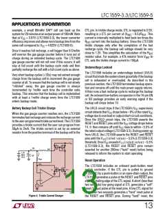
Battery Backup Cell Trickle Charge
The UVLO circuit trips if the LTC1559’s VCC supervisory
circuit detects that VCC drops below –9% of the rated VCC
voltage due to overload or output short-circuit conditions.
Once the UVLO circuit trips, the LTC1559 asserts the
RESET and RESET pins until the VCC voltage drops below
1V. It then remains off until VCC rises to within –5.5% of
the rated output voltage (LTC1559-3.3). During power-up
from UVLO, the LTC1559 asserts the RESET and RESET
pins until the VCC(rated value) – 5.5%(LTC1559-3.3)
threshold. Once VCC exceeds VCC(rated value) – 5.5%
(LTC1559-3.3), the RESET and RESET pins remain
asserted for another 200ms (“hard” reset) before being
released to inform the system to start operating.
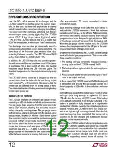
When the gas gauge counter reaches zero, the LTC1559
terminatesfastrechargeandreducestherechargecurrent
totheuser-programmedtricklecurrentlevel.TheLTC1559
provides a trickle current that the user can program from
50µA to 2mA. The trickle current is set by an external
resistor from the positive terminal of the backup cell to the
V
CC
10I
SW
1.2V
NiCd
CELL
+
I
1µF
R
EXT
Reset Operation
CTL
The LTC1559 includes an onboard push-button reset
switch controller. If the CTL pin is pulled to ground
(<250mV) by a push-button or an open-drain output, the
LTC1559 generates a pulse at the RESET and RESET pins
after the trailing edge of the CTL signal. A short (less than
two seconds) low going signal at CTL generates a “soft”
reset (100µs) pulse at the reset pins. A low CTL signal for
more than two seconds generates a “hard” reset pulse at
the RESET and RESET pins. During “hard” reset, the
1×
11×
–
+
+
0.5V
–
LTC1559
1559 F04
Figure 4. Trickle Current Charger
13

 Linear [ Linear ]