LTC1559-3.3/LTC1559-5
U
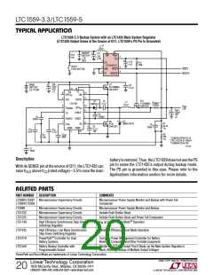
TYPICAL APPLICATION
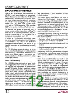
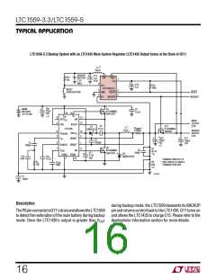
LTC1559-3.3 Backup System with an LTC1435 Main System Regulator (LTC1435 Output Sense at the Drain of Q11)
†
L11
22µH
1
SW
8
BACKUP
BATTERY
1.2V
+
C11
1µF
6.3V
R14
14k
V
BAK
7
V
CC
+
NiCd
3
C12
1µF
R15
100k
CTL
LTC1559-3.3
RESET
2
4
5
6
GND
RESET
RESET
PUSH-BUTTON
PS
BACKUP
BACKUP
C
IN
Q1
MAIN
BATTERY
4.5 TO 28V
+
C2
22µF
35V
× 2
N-CHANNEL
Si4412DY
0.1µF
13 16
TG
SW
V
EXTV
IN
14
15
9
4
CC
MAIN
OUTPUT
3.3V
SFB
BOOST
LTC1435
INTV
C4
0.1
Q11
P-CHANNEL
Si9424Y
D1
CMDSH-3
L1*
R
SENSE**
µF
10µH
BACKUP
OUTPUT
3.3V
0.033Ω
6
3
12
8
V
OSENSE
CC
+
C
+
OUT
+
C15
100µF
10V
I
SENSE
TH
C5
1000pF
100µF
10V
C
C
2
1
7
–
RUN/SS SENSE
330pF
×2
Q2
R1
35.7k
1%
11
C6
C
BG
SGND PGND
N-CHANNEL
Si4412DY
OSC
C3
100pF
+
D2
4.7
µF
C
C
0.1
MBRS140T3
C2
SS
µ
16V
5
10
51pF
F
*SUMIDA CDRH125-10
R
R5
20k
1%
C
OSC
68pF
**IRC LR2010-01-R033-F
C
†
10k
SUMIDA CD54-220
1559 TA03
C1
100pF
Description
during backup mode, the LTC1559 deasserts its BACKUP
pin and returns control back to the LTC1435. Q11 turns on
and allows the LTC1435 to charge C15. Please refer to the
Applications Information section for more details.
ThePSpinconnectstoQ11’sdrainandallowstheLTC1559
to detect the restoration of the main battery during backup
mode. Once the LTC1435’s output is greater than VOUT
16

 Linear [ Linear ]