LTC1410
W
U
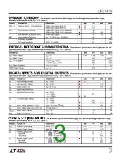
The ● denotes specifications which apply over the full operating temperature range,
DY
A IC
ACCURACY
otherwise specifications are at TA = 25°C. (Note 5)
SYMBOL
PARAMETER
CONDITIONS
MIN
TYP
MAX
UNITS
S/(N + D)
Signal-to-(Noise + Distortion) Ratio
100kHz Input Signal (Note 12)
600kHz Input Signal (Note 12)
●
●
70
68
72.5
71.0
dB
dB
THD
Total Harmonic Distortion
100kHz Input Signal, First 5 Harmonics
600kHz Input Signal, First 5 Harmonics
–85
–82
dB
dB
●
●
–74
–74
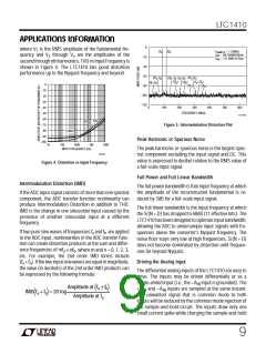
Peak Harmonic or Spurious Noise
Intermodulation Distortion
Full Power Bandwidth
600kHz Input Signal
–84
–84
20
dB
dB
IMD
f
IN1
= 29.37kHz, f = 32.446kHz
IN2
MHz
MHz
Full Linear Bandwidth
(S/(N + D) ≥ 68dB)
2.5
U U
U
I TER AL REFERE CE CHARACTERISTICS The ● denotes specifications which apply over the full
operating temperature range, otherwise specifications are at TA = 25°C. (Note 5)
PARAMETER CONDITIONS
MIN
TYP
2.500
±15
MAX
UNITS
V
V
Output Voltage
Output Tempco
Line Regulation
I
= 0
= 0
2.480
2.520
REF
OUT
V
REF
I
ppm/°C
OUT
V
REF
4.75V ≤ V ≤ 5.25V
0.01
0.01
LSB/V
LSB/V
DD
–5.25V ≤ V ≤ –4.75V
SS
V
REF
Output Resistance
I
≤ 0.1mA
2
kΩ
OUT
COMP Output Voltage
I
= 0
4.06
V
OUT
U
U
DIGITAL I PUTS A D DIGITAL OUTPUTS The ● denotes specifications which apply over the full
operating temperature range, otherwise specifications are at TA = 25°C. (Note 5)
SYMBOL PARAMETER CONDITIONS
MIN
TYP
MAX
UNITS
V
V
High Level Input Voltage
Low Level Input Voltage
Digital Input Current
V
= 5.25V
= 4.75V
DD
●
●
●
2.4
IH
DD
V
IL
V
0.8
V
I
IN
V
IN
= 0V to V
DD
±10
µA
pF
C
Digital Input Capacitance
High Level Output Voltage
5
IN
V
OH
V
DD
= 4.75V
I = –10µA
I = –200µA
O
4.5
V
V
O
●
4.0
V
Low Level Output Voltage
V
= 4.75V
I = 160µA
I = 1.6mA
OL
DD
0.05
0.10
V
V
O
●
●
●
0.4
±10
15
O
I
OZ
High-Z Output Leakage D11 to D0
High-Z Output Capacitance D11 to D0
Output Source Current
V
OUT
= 0V to V , CS High
µA
pF
DD
C
OZ
CS High (Note 9 )
= 0V
I
V
–10
10
mA
mA
SOURCE
OUT
I
Output Sink Current
V
= V
SINK
OUT DD
W U
POWER REQUIRE E TS The ● denotes specifications which apply over the full operating temperature range,
otherwise specifications are at TA = 25°C. (Note 5)
SYMBOL PARAMETER
CONDITIONS
(Notes 10, 11)
(Note 10)
MIN
4.75
TYP
MAX
5.25
UNITS
V
V
Positive Supply Voltage
Negative Supply Voltage
DD
V
SS
–4.75
–5.25
V
I
Positive Supply Current
Nap Mode
Sleep Mode
CS = RD = CONVST = 5V
SHDN = 0V, NAP/SLP = 5V
SHDN = 0V, NAP/SLP = 0V
●
●
12
1.5
1
16
2.3
100
mA
mA
µA
DD
I
SS
Negative Supply Current
Nap Mode
Sleep Mode
CS = RD = CONVST = 5V
SHDN = 0V, NAP/SLP = 5V
SHDN = 0V, NAP/SLP = 0V
20
10
1
30
200
100
mA
µA
µA
3

 Linear [ Linear ]