LTC1255
APPLICATIO S I FOR ATIO
U U
W
U
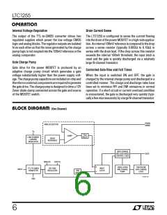
The switches can either be turned OFF by the controlling
logic during these transients or latched OFF above 30V by
holding the drain sense pin low as shown in Figure 9.
14V
+
D1
1µF
50V
MR2535L
R
SENSE
0.036Ω
V
S
1k*
DS1
1/2 LTC1255
IN1
Switch status can be ascertained by means of an XNOR
gate connected to the input and switch output through
100k current limiting resistors (see Typical Applications
sectionformoredetailonthisscheme).Theswitchisreset
after the overvoltage event by cycling the input low and
then high again.
10k
FROM
µP, ETC.
IRF530
G1
12V
GND
1N5242B
30V*
1N5256B
LOAD
100Ω
LTC1255 • F09
The power MOSFET switch should be selected to have a
breakdown voltage sufficiently higher than the 40V supply
clampvoltagetoensurethatnocurrentisconductedtothe
load during the transient.
*OPTIONAL OVERVOLTAGE (30V) LATCH-OFF COMPONENTS
Figure 9. Overvoltage Transient Protection
U
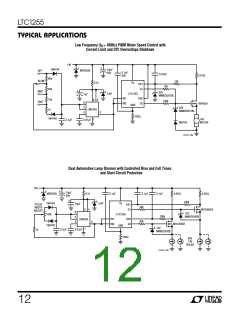
TYPICAL APPLICATIO S
Dual Automotive High-Side Switch with Overvoltage Protection,
XNOR Status and 12µA Standby Current
14V
+
1µF
MR2535L*
50V
0.036Ω
0.036Ω
V
S
DS1
G1 LTC1255 G2
IN1 IN2
DS2
10k
10k
10k** MTD3055E
MTD3055E
10k**
12V
MMBZ5242B
12V
MMBZ5242B
100k
100k
GND
14V/1A
SOLENOID
14V/1A
SOLENOID
1N5400
1N5400
1/4 74C266†
1/4 74C266†
100Ω
FAULT FROM
TO µP µP, ETC.
FROM FAULT
µP, ETC. TO µP
LTC1255 • TA03
TRUTH TABLE
IN OUT
*LIMITS V TRANSIENTS TO <40V. SEE MANUFACTURER DATA SHEET FOR
S
CONDITION
SWITCH OFF
OVERCURRENT
OPEN LOAD**
SWITCH ON
FAULT
FURTHER DETAIL.
0
1
0
1
0
0
1
1
1
0
0
1
**OPTIONAL OPEN LOAD DETECTION REQUIRES 10k PULL-UP RESISTORS.
(ULTRA LOW STANDBY QUIESCENT CURRENT IS SACRIFICED)
†
POWER FROM 5V LOGIC SUPPLY.
10

 Linear [ Linear ]