LT3587
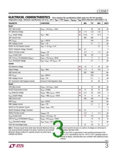
ELECTRICAL CHARACTERISTICS The l denotes the specifications which apply over the full operating
temperature range, otherwise specifications are at TA = 25°C. VVIN = 3.6V, VEN/SS1 = VEN/SS3 = VVIN unless otherwise noted (Note 2, 3).
PARAMETER
CONDITIONS
MIN
TYP
MAX
UNITS
Boost1
CAP1 Bias Current
FB1 Reference Voltage
V
= 15V, V
= Open
OUT1
60
1.22
15
150
1.25
μA
V
CAP1
l
l
1.19
14.25
800
V
Output Voltage
R
= 1MΩ
15.75
V
OUT1
FB1
SW1 Current Limit
SW1 V
990
200
0.1
mA
mV
μA
V
I
= 400mA
= 15V
CESAT
SW1
SW1 Leakage Current
V
V
5
SW1
EN/SS1 for Full Inductor Current
EN/SS1 Shutdown Voltage Threshold
EN/SS1 Pin Bias Current
= 1.1V, V = 0.1V
2.5
FB1
FB2
l
0.2
–0.5
100
V
V
V
V
= 0V
–1
155
5
–1.5
μA
mA
Ω
EN/SS1
V
OUT1
Current Limit
= 15V
CAP1
CAP1
CAP1 to V
On-Resistance (R
)
= 15V, I = 50mA
VOUT1
8
1
OUT1
DISC1
V
Disconnect Leakage
V
VIN
= V
= 6V, V = 0V
VOUT1
0.1
μA
OUT1
CAP1
Inverter
l
l
FB2 Reference Voltage
Output Voltage
SW2 Current Limit
–10
–7.5
900
5
–8
20
mV
V
R
= 1Mꢀ
–8.5
FB2
1090
250
0.1
87
mA
mV
μA
%
SW2 V
I
= 600mA
= 15V
CESAT
SW2
SW2 Leakage Current
V
SW2
5
FB1 Threshold to Start Negative Channel
Boost3
Percent of Final Regulation Value
90
CAP3 Bias Current
V
= 15V, V
= Open
OUT3
70
20
150
22
μA
mA
V
CAP3
l
l
l
Boost3 Programmed Current
R
= 8.06kꢀ
= 1Mꢀ, I
= 1Mꢀ, I
18
0.77
14
IFB3
V
V
Reference Voltage
R
= 20mA
0.8
15
0.83
16
FB3
VFB3
VOUT3
VOUT3
Output Voltage
R
= 20mA
V
OUT3
VFB3
SW3 Current Limit
SW3 V
400
480
250
0.1
mA
mV
μA
V
I
= 200mA
SW3
CESAT
SW3 Leakage Current
V
= 15V
5
2
SW3
EN/SS3 for Full Inductor Current
EN/SS3 Shutdown Voltage Threshold
EN/SS3 Pin Bias Current
V
= V
= 0.6V
VFB3
IFB3
l
0.2
–0.5
70
V
V
= 0V
–1
110
10
–1.5
μA
mA
ꢀ
EN/SS3
V
OUT3
Current Limit
V
= 15V, V
= 0V
CAP3
CAP3
IFB3
CAP3 to V
On Resistance (R
)
V
= 15V, I
= 20mA
15
1
OUT3
DISC3
VOUT3
V
OUT3
Disconnect Leakage
V
= V
= 6V, V = 0V
VOUT3
0.1
29
μA
V
VIN
CAP3
CAP3 Pin Overvoltage Clamp
27
31
Note 1: Stresses beyond those listed under Absolute Maximum Ratings
may cause permanent damage to the device. Exposure to any Absolute
Maximum Rating condition for extended periods may affect device
reliability and lifetime.
Note 2: All currents into pins are positive; all voltages are referenced to
GND unless otherwise noted.
Note 3: The LT3587 is guaranteed to meet specified performance from
0°C to 125°C. Specifications over the –40°C to 125°C operating range are
assured by design, characterization and correlation with statistical process
controls.
3587fc
3

 Linear [ Linear ]