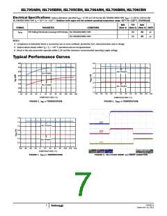
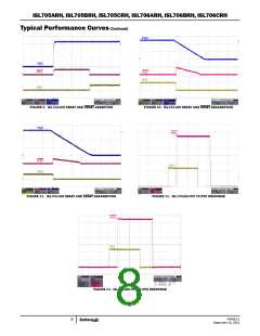
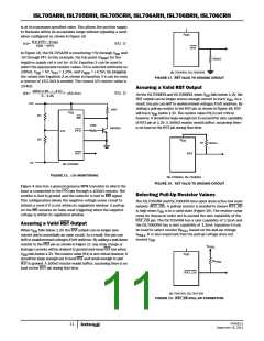
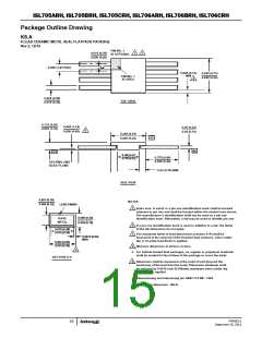
ISL705ARH, ISL705BRH, ISL705CRH, ISL706ARH, ISL706BRH, ISL706CRH
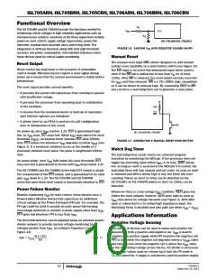
Package Outline Drawing
K8.A
8 LEAD CERAMIC METAL SEAL FLATPACK PACKAGE
Rev 2, 12/10
PIN NO. 1
ID OPTIONAL
0.015 (0.38)
0.008 (0.20)
1
2
0.050 (1.27 BSC)
0.005 (0.13)
0.265 (6.73)
0.245 (6.22)
MIN
PIN NO. 1
ID AREA
4
0.022 (0.56)
0.015 (0.38)
TOP VIEW
0.115 (2.92)
0.070 (1.18)
0.045 (1.14)
0.026 (0.66)
0.09 (0.23)
0.04 (0.10)
6
0.265 (6.75)
0.245 (6.22)
-D-
-H-
-C-
0.180 (4.57)
0.170 (4.32)
0.370 (9.40)
0.250 (6.35)
SEATING AND
BASE PLANE
0.03 (0.76) MIN
SIDE VIEW
0.007 (0.18)
0.004 (0.10)
NOTES:
LEAD FINISH
Index area: A notch or a pin one identification mark shall be located
adjacent to pin one and shall be located within the shaded area shown.
The manufacturer’s identification shall not be used as a pin one
identification mark. Alternately, a tab may be used to identify pin one.
1.
0.009 (0.23)
0.004 (0.10)
BASE
METAL
2. If a pin one identification mark is used in addition to a tab, the limits
of the tab dimension do not apply.
0.019 (0.48)
0.015 (0.38)
3. The maximum limits of lead dimensions (section A-A) shall be
measured at the centroid of the finished lead surfaces, when solder
dip or tin plate lead finish is applied.
0.0015 (0.04)
MAX
0.022 (0.56)
0.015 (0.38)
4. Measure dimension at all four corners.
3
5. For bottom-brazed lead packages, no organic or polymeric materials
shall be molded to the bottom of the package to cover the leads.
SECTION A-A
6. Dimension shall be measured at the point of exit (beyond the
meniscus) of the lead from the body. Dimension minimum shall
be reduced by 0.0015 inch (0.038mm) maximum when solder dip
lead finish is applied.
7. Dimensioning and tolerancing per ANSI Y14.5M - 1982.
8. Controlling dimension: INCH.
FN7662.0
September 15, 2011
15

 INTERSIL [ Intersil ]