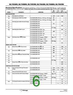
ISL705ARH, ISL705BRH, ISL705CRH, ISL706ARH, ISL706BRH, ISL706CRH
Functional Overview
R
1
The ISL705xRH and ISL706xRH provide the functions needed for
monitoring critical voltages in high reliability applications such as
microprocessor systems. Functions of the these supervisors include
power-on reset control; supply voltage supervisions; power-fail
detection; manual-reset assertion and a watch dog timer. The
integration of all these functions along with their high threshold
accuracy, low power consumption, and radiation tolerance make
these devices ideal for critical supply monitoring.
V
PFI
IN
R
2
ISL705xRH/ISL706xRH
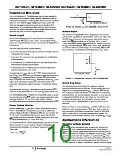
FIGURE 14. CUSTOM V WITH RESISTOR DIVIDER ON PFI
TH
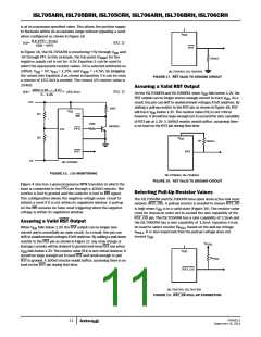
Manual Reset
The manual reset input (MR) allows designers to add manual
system reset capability via a push button switch (see Figure 15).
The MR input is an active low debounced input which asserts
Reset Output
Reset control has long been a critical aspect of embedded
control design. Microprocessors require a reset signal during
power up to ensure that the system environment is stable before
initialization.
reset if the MR pin is pulled low to less than V for at least
IL
150ns. After MR is released, the reset output remains asserted
for t
and then released. MR is a TTL/CMOS logic compatible,
RST
so it can be driven by external logic. By connecting WDO to MR,
one can force a watchdog time out to generate a reset pulse.
The reset signal provides several benefits:
• It prevents the system microprocessor from starting to operate
with insufficient voltage.
• It prevents the processor from operating prior to stabilization
of the oscillator.
20k
MR
• It ensures that the monitored device is held out of operation
until internal registers are initialized.
• It allows time for an FPGA to perform its self configuration
prior to initialization of the circuit.
PB
On power-up, once V reaches 1.2V, RST is guaranteed logic
DD
ISL705xRH/ISL706xRH
low. As V rises, RST stays low. When V rises above the reset
DD
DD
threshold (V
), an internal timer releases RST after 200ms
RST
FIGURE 15. CONNECTING A MANUAL RESET PUSH-BUTTON
(typ). RST pulses low whenever V degrades to below V
(see
DD
RST
Figure 3). If a brownout condition occurs in the middle of a
Watch Dog Timer
The watchdog time circuit checks for coherent program
previously initiated reset pulse, the pulse is lengthened 200ms
(typ).
execution by monitoring the WDI pin. If the processor does not
On power-down, once V falls below the reset threshold, RST
DD
toggle the watchdog input within t
(1.0s min), WDO will go
WD
stays low and is guaranteed to be low until V drops below 1.2V.
DD
low. As long as reset is asserted or the WDI pin is tri-stated, the
watchdog timer will stay cleared and not count. As soon as reset
is released and WDI is driven high or low, the timer will start
counting. Pulses as short as 50ns can be detected on the
ISL705xRH, on ISL706xRH pulses as short as 100ns can be
detected.
The ISL705BRH and ISL706BRH active-high RST output is simply
the complement of the RST output, and is guaranteed to be valid
with V down to 1.2V. The ISL705CRH and ISL706CRH
DD
active-low open-drain reset output is functionally identical to RST.
Power Failure Monitor
Whenever there is a low-voltage V condition, WDO goes low.
DD
Unlike the reset outputs, however, WDO goes high as soon as
Besides monitoring V for reset control, these devices have a
DD
Power-Failure Monitor feature that supervises an additional
critical voltage on the Power-Fail Input (PFI) pin. For example, the
PFI pin could be used to provide an early power-fail warning,
V
rises above its voltage trip point (see Figure 4). With WDI
DD
open or connected to a tri-stated high impedance input, the
Watchdog Timer is disabled and only pulls low when V < V
.
DD
RST
overvoltage detection or monitor a power supply other than V
.
DD
PFO goes low whenever PFI is less than V
.
PFI
Applications Information
Negative Voltage Sensing
The threshold detector can be adjusted using an external resistor
divider network to provide custom voltage monitoring for
voltages greater than V , according to Equation 1 (see
This family of devices can be used to sense and monitor the
PFI
Figure 14).
presence of both a positive and negative rail. V is used to
DD
monitors the positive supply while PFI monitors the negative rail.
PFO is high when the negative rail degrades below a V value
R1 + R2
R2
⎛
⎝
⎞
⎠
---------------------
(EQ. 1)
VIN = V
PFI
TRIP
value.
and remains low when the negative rail is above the V
trip
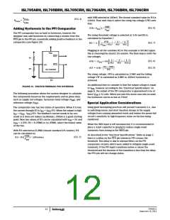
As the differential voltage across the R1, R2 divider is increased,
the resistor values must be chosen such that the PFI node is
<1.25V when the -V supply is satisfactory and the positive supply
FN7662.0
September 15, 2011
10

 INTERSIL [ Intersil ]