HI2555, CXD2555
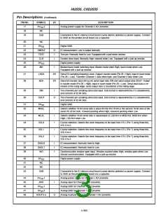
Pin Descriptions (Continued)
PIN NO.
17
SYMBOL
AV
I/O
DESCRIPTION
2
-
-
-
Analog power supply for Channel-2 AD converter.
DD
18
NC
19
SUB
Connected to the IC internal circuit board (same electric potential as power supply). Connect
to GND on the printed circuit board via a capacitor.
20
21
22
23
24
25
26
NC
-
-
DV
SS
Digital GND.
XMCK2
TEST
CLR
O
I
IC measurement. Low is output normally.
Test pin. Normally fixed to Low. Equipped with a pull-down resistor.
System clear input. Normally High; cleared when Low. Equipped with a pull-up resistor.
Digital power supply.
I
DV
-
DD
MS
I
Master/slave mode switching input. Master mode when High; slave mode when Low.
Equipped with a pull-up resistor.
27
28
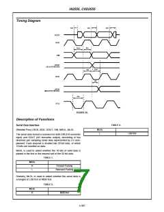
LRCK
BCK
I/O
I/O
Serial I/O sampling frequency clock. Output i master mode (Pin 26 = High); input in slave mode
(Pin 26 = Low). Transfers Channel-1 data when high, and Channel-2 data when Low.
Serial bit transfer clock (64 f ) for serial input data SIN and serial output data SOUT. Output
S
in master mode (Pin 26 = High); input in slave mode (Pin 26 = Low). Serial input data is re-
trieved at the rising edge; serial output data is transferred at the falling edge.
29
30
SIN
I
Two channels per sampling serial data input. Data format is represented by 2’s complements,
and consists of 32-bit slots.
SOUT
O
Two channels per sampling serial data input. Data format is represented by 2’s complements,
and consists of 32-bit slots.
31
32
DV
SS
-
I
Digital GND.
MASL
MLSL
XSL0
XSL1
XSL2
Selects whether 16-bit serial data is place din the first 16-bit or the second 16-bit slots of the
serial I/O 32-bit slots. Forward packing when High; rearward packing when Low.
33
34
35
36
I
I
I
I
Selects whether 16-bit serial data is input/output at LSB-first or MSB-first. MSB-first when
High; LSB-first when Low.
Crystal selection. Selects the clock frequency to be input from XTLI (Pin 7) using three bits,
XSL 0 to 2.
Crystal selection. Selects the clock frequency to be input from XTLI (Pin 7) using three bits,
XSL 0 to 2.
Crystal selection. Selects the clock frequency to be input from XTLI (Pin 7) using three bits,
XSL 0 to 2.
37
38
39
DASL0
DASL1
WO
I
I
I
IC measurement. Normally fixed to High.
IC measurement. Normally fixed to Low.
Synchronization window open input. Window masked when High; window open when Low
(forced synchronization). Equipped with a pull-up resistor.
40
41
42
43
DV
-
-
-
-
Digital power supply
DD
NC
NC
SUB
Connected to the IC internal circuit board (same electric potential as power supply). Connect
to GND on the printed circuit board via a capacitor.
44
45
46
47
48
AV
1
-
I
Analog power supply for Channel-1 AD converter.
Analog input for Channel-1 AD converter.
Analog GND for Channel-1 AD converter.
Analog GND for Channel-1 DA converter.
Analog in-phase output for Channel-1 DA converter.
DD
AIN1
AV
1
3
-
SS
AV
-
SS
AOUT1(+)
O
4-303

 INTERSIL [ Intersil ]